One thing that irritates me to no end is to look at a set of geotechnical plans and to realise that there is only one boring for the entire site. In a few cases that’s enough, but very few. The “uniform site conditions” of academic legend are seldom found in real life; soil conditions vary from one place to another on a site and in some stratigraphies in a matter of feet or metres. If it’s worth sending a crew out to a site for one or two borings it’s worth getting more.
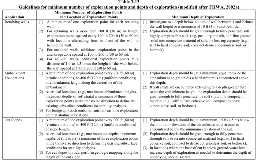
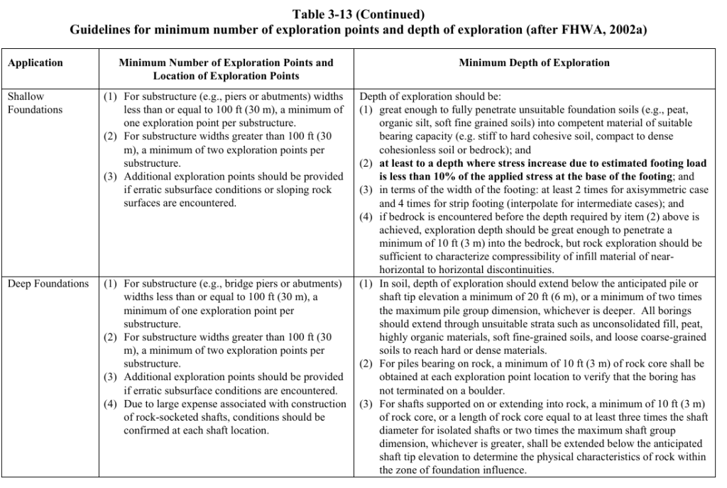
The table “Guidelines for minimum number of exploration points and depth of exploration” is shown below, and is taken from the Soils and Foundations Reference Manual, which has much additional information on this and other related topics. It also deals with another issue that bedevils geotechnical exploration: going deep enough to get the information needed, especially with deep foundations. I also spent a great deal of time on this subject in my course Foundation Design and Analysis: Boring Logs and Their Interpretation, evidently more than other undergraduate courses.
A couple of years ago our bookstore was reorganised to put our offerings in wider distribution. Some of the discontinued titles are being put back into print, directly from the printer. Click on the title or image to to order.
This manual presents guidelines for calculation of the bearing capacity of soil under shallow and deep foundations supporting various types of structures and embankments. Principles for evaluating bearing capacity presented in this manual are applicable to numerous types of structures such as buildings and houses, towers and storage tanks, fills, embankments and dams. These guidelines may be helpful in determining soils that will lead to bearing capacity failure or excessive settlements for given foundations and loads. Consideration should be given to obtaining the services and advice of specialists and consultants in foundation design where foundation conditions are unusual or critical or structures are economically significant.
Settlement Analysis
This manual presents guidelines for calculation of vertical displacements and settlement of soil under shallow foundations (mats and footings) supporting various types of structures and under embankments. Vertical displacements and settlement caused by change in stress and water content are described in this manual. Limitations of these movements required for different structures are also described. Various types of settlement are discussed in detail, including settlement due to elastic deformation, consolidation, secondary compression and creep, settlement due to dynamic loads, and expansive and collapsible soils. Solutions to soil movement problems are discussed and detailed. Deep foundations and landfills are also discussed.
This book presents information on the design of retaining walls and inland and coastal flood walls. Retaining walls are defined as any wall that restrains material to maintain a difference in elevation.
A floodwall is defined as any wall having as its principal function the prevention of loading of adjacent land. Not specifically covered in this book are seawalls which are defined as structures separating land and water areas, primarily designed to prevent erosion and other damage due to wave action. They are frequently built at the edge of the water, but can be built inland to withstand periods of high water.
Seawalls are generally characterized by a massive cross section and a seaward face shaped to dissipate wave energy. Coastal flood walls, however, are generally located landward of the normal high water line so that they are inundated only by hurricane or other surge tide and have the smooth-faced cantilever stems shown in this book. This book also describes procedures for the design of retaining and flood walls on shallow foundations, i.e., those bearing directly on rock or soil.
This book deals with the soil mechanics aspects of the design of waterfront retaining structures built to withstand the effects of earthquake loadings. It addresses the stability and movement of gravity retaining walls and anchored sheet pile walls, and the dynamic forces against the walls of drydocks and U-frame locks. It also contains one of the most complete descriptions of lateral earth pressure theory available anywhere.
The effects of wall displacements, submergence, liquefaction potential, and excess pore water pressures, as well as inertial and hydrodynamic forces, are incorporated in the design procedures. Several new computational procedures are described in this report.
The procedures used to calculate the dynamic earth pressures acting on retaining structures consider the magnitude of wall displacements. For example, dynamic active earth pressures are computed for walls that retain yielding backfills, i.e., backfills that undergo sufficient displacements during seismic events to mobilize fully the shear resistance of the soil. For smaller wall movements, the shear resistance of the soil is not fully mobilized and the dynamic earth pressures acting on those walls are greater because the soil comprising the backfill does not yield, i.e., a nonyielding backfill. Procedures for incorporating the effects of submergence within the earth pressure computations, including consideration of excess pore water pressures, are described.
Originally written to supply engineer officers and noncommissioned officers with doctrinal tenets and technical facts concerning the use and management of soils during military construction, Military Soils Engineering is one of the most practical guides to basic engineering geology and soil mechanics available. It provides guidance in evaluating soil conditions, predicting soil behavior under varying conditions, and solving soil problems principally related to military operations but applicable to the construction of a wide variety of foundations and earth structures.
Construction in a military theater of operations is normally limited to roads, airfields, and structures. This manual emphasizes the soils engineering aspects of road and airfield construction. The references included in the manual give detailed information on other soils engineering topics that are discussed in general terms.
In addition to this, the manual:
Provides a discussion of the formation and characteristics of soil and the Unified System of soil classification, used by the United States (US) Army and most geotechnical engineers;
Gives an overview of classification systems used by AASHTO and the Department of Agriculture;
Describes the compaction of soils and quality control, settlement and shearing resistance of soils;
Describes the movement of water through soils, frost action, and the bearing capacity of soils that serve as foundations, slopes, embankments, dikes, dams, and earth-retaining structures; and
Has a detailed description of the geologic factors that affect the properties and occurrences of natural mineral/soil construction materials used to build a wide variety of structures.
Military Soils Engineering is an indispensable reference for geotechnical engineers, engineering geologists and laboratory and field technicians.
This is a combination of two authoritative documents on this vital subject.
Federal Guidelines for Dam Safety (FEMA 93): These guidelines apply to management practices for dam safety of all Federal agencies responsible for the planning, design, construction, operation, or regulation of dams. They are not intended as guidelines or standards for the technology of dams. The basic principles of the guidelines apply to all dams. However, reasonable judgments need to be made in their application commensurate with each dam’s size, complexity, and hazard. Federal agencies have a good record and generally sound practices on dam safety. These guidelines are intended to promote management control of dam safety and a common approach to dam safety practices by all the agencies. Although the guidelines are intended for and applicable to all agencies, it is recognized that the methods of the degree of application will vary depending on the agency mission and functions.
Safety of Dams—Policy and Procedures (U.S. Army Corps of Engineers ER 1110-2-1156): This regulation prescribes the guiding principles, policy, organization, responsibilities, and procedures for implementation of risk- informed dam safety program activities and a dam safety portfolio risk management process within the United States Army, Corps of Engineers (USACE). Risk is defined as a measure of the probability and severity of undesirable consequences or outcome. The purpose and intent of this regulation is to ensure that responsible officials at all levels within the Corps of Engineers implement and maintain a strong dam safety program in compliance with “Federal Guidelines for Dam Safety.” The program ensures that all dams and appurtenant structures are designed, constructed, and operated safely and effectively under all conditions, based on the following dam safety and dam safety program purposes, as adopted by the Interagency Committee on Dam Safety (ICODS).
Of all the topics I taught in my course on foundation design and analysis, my favourite topic was driven piles. I have taken this part of the course and am presenting it on the companion site vulcanhammer.info. The topics are as follows:
In putting this together, I added some material, including a different example problem and actual runs of axial and lateral load software, along with the wave equation analysis.
I trust that you will find this enjoyable and profitable.
My post Getting to the Legacy of B.K. Hough and his Settlement Method got a good amount of interest. Unfortunately it left several “loose ends,” some of which is because we don’t have full information on some of Hough’s methodology, and others because we don’t have full information on the FHWA’s thinking in their resurrection of the method. The objective of this post is to clear up some of these loose ends, especially the latter.
What we needed was some additional information on the background for both Hough’s work and the FHWA’s interpretation of that work. That information came from an unexpected source: the FHWA’s Design and Construction of Driven Pile Foundations, 2016 Edition. This has been available on vulcanhammer.info just about since it was first published. Now some of you are asking, “Why is this guy waiting until now to come out with stuff he’s had for years? Doesn’t he read the material he offers for download?” In my defence, I didn’t expect the solution to come from the driven pile manual, since it’s primarily a shallow foundation issue. It’s there because it’s proposed for use with groups of driven piles in cohesionless soils.
With all that said let’s look at some of the issues this “new” source tackles.
The SPT Correction Issue
The basic equation for Hough’s method is similar to that used for one-dimensional consolidation settlement and is
(1)
where
settlement of cohesionless soil layer
layer thickness
compression coefficient
effective stress at the centre of the layer
effective stress at the centre of the layer plus the induced stress from the surface at the centre of the layer
Hough’s Method may or may not have used a 60% (N60) efficient hammer to develop the method. It’s entirely possible but Hough (1959) doesn’t say what type of hammer he used to develop the method.
The FHWA implementation of Hough’s method included an SPT correction for overburden, which was absent in Hough (1959.)
An absence of any mention of Hough (1969,) where he modified the values.
The lack of an attempt to convert the chart to equations. My original post demonstrates how this can be done, using the method of Hough (1969.)
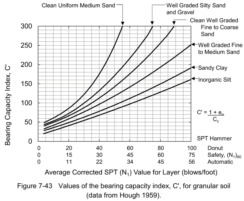
Cheney and Chassie (2002) report that FHWA experience with this method indicates the method is usually conservative and can overestimate settlements by a factor of 2. This conservatism is attributed to the use of the original bearing capacity index chart from Hough (1959) which was based upon SPT donut hammer data. Based upon average energy variations between SPT donut, safety, and automatic hammers reported in technical literature, Figure 7-43 now includes a correlation between SPT N values from safety and automatic hammers and bearing capacity index. The safety hammer values are considered N60 values. This modification should improve the accuracy of settlement estimates with this method.
The following should be noted about these changes:
The assumption that Hough used a “donut” hammer is a reasonable one based on the technology of the time, but it’s still an assumption. Hough doesn’t tell us the kind of SPT hammer he used, or even how he came up with the C’ values shown above.
The chart above (Figure 7-43) shows the correlation for three types of hammers: donut, safety, and automatic hammers (which now “rule the roost” in testing.) However, it still insist that the safety hammer values should be corrected for overburden, something else absent from Hough’s study.
There is still no awareness of Hough (1969.)
So we can say that we have, perhaps, made some progress toward a solution, but at this point we are not quite where we would like to be.
My Thinking on the Way Forward
We usually think in terms of progress in this field in terms of peer-reviewed articles. But we’ve had the peer-reviewed articles, the experts weigh in on what they mean, and another set of experts try to make things better. My own solution to this problem would run like this:
Let’s accept the FHWA’s idea that Hough used a donut hammer for his original work. Donut hammers have a “standard” efficiency of 45%. To get the SPT blow counts to an N60 value (60% efficiency) we need to divide the donut SPT values by 60/45 = 4/3. (That’s what’s going on in the graph above.)
Let’s use Hough’s method as he presented it in Hough (1969) and assume that those values too came from donut hammers.
Let’s lose the overburden correction; it wasn’t in the original and I don’t see how one can justify putting it into this method.
If we implement all of this, the chart now looks like this:
If formulae are preferred (and that’s normally the case these days) they will again be in the form
(2)
and the coefficients will be as follows:
Soil Type
A
B
Organic Silt, Little Clay
7.22
0.0305
Inorganic Sandy Silt
18.27
0.0279
Very Well Graded Fine to Coarse Sand
22.86
0.0270
Well Graded Clean Fine to Coarse Sand
28.22
0.0289
Well Graded Silty Sand and Gravel
32.85
0.0289
Uniform Clean Inorganic Silt
37.02
0.0294
Very Uniform Clean Medium Sand (Similar to Std. Ottawa)
58.66
0.0299
The “B” coefficients run in a fairly narrow range and have an average of 0.0289. It’s possible using this or a more sophisticated method to apply the same value of B to all of the soils.
Any comments from those of you who have used Hough’s Method, or have research on the topic, would be greatly appreciated.
References
Hough, B.K. (1959). “Compressibilty as the Basis for Soil Bearing Value,” Journal of the Soil Mechanics and Foundations Division, ASCE, Vol. 85, Part 2.
Hough, B.K. (1969). Basic Soils Engineering. Second Edition. New York: Ronald Press Company.
One of those “things” in geotechnical engineering that looks like “settled science” but may not be is the whole business of lateral earth pressures for braced cuts. (An example of one is shown at the right.) Textbooks of all kinds (including Soils in Construction) show pressure profiles and solution techniques that are “definitive.” Or are they? This article is more about asking questions than delivering another round of “definitive” answers, but hopefully it will at least spark some thought and perhaps make practitioners more careful in their application of these methods.
The Basic Problem
Based on experience, first in Berlin and later in Chicago, Terzaghi (and later also Ralph Peck) developed a set of pressure distributions as shown at the left. These are at variance with those usually associated with retaining walls in general and sheet pile walls in particular. The theory behind these (certainly for the clays) had its genesis in Rankine theory adapted for cohesive soils, but the distribution is rather different. These distributions have been reproduced in many textbooks and reference books, including Soils in Construction and Sheet Pile Design by Pile Buck.
It’s worth noting that there are other pressure distributions that have been formulated other than the ones shown above, as outlined by Boone and Westland (2005).
Along with the distributions came the method of using them: the “hinged method” of analysing the sheet pile wall. Strictly speaking the sheet pile wall is a continuous beam with multiple supports. Since there are usually more than two struts and supports, to use a continuous beam requires a statically indeterminate beam. Applying hinges (as shown at the right) can make the beam statically determinate. Although methods for solving statically indeterminate beams existed in Terzaghi’s day (remember it was geotechnical methods which then and now lag the rest of civil engineering in advancement,) converting the problem to a statically determinate one was convenient for computational purposes.
But then comes the kicker: as generally presented, if the distributions above are used, they must be used with the hinged method, even when analysing a braced cut wall using a braced cut method with a continuous beam is nearly trivial now. Why is this?
How It Came About
Like so many things in civil engineering, the investigation of pressures on braced cuts came about as a result of tragedy. As noted by Rogers (2013):
On the evening of December 1, 1938 Terzaghi delivered a terse lecture titled “The danger of excavating subways in soft clays beneath large cities.” The lecture focused on his recent experiences with construction of the Berlin Subway, which was hampered by a high water table in running sands. These conditions had contributed to the sudden failure of a shored excavation which killed 20 workers in August 1935. He made a convincing case for proper geotechnical oversight during construction if similar tragedies were to be avoided in Chicago.
The lecture with its graphic images of the dead bodies beneath the collapsed bulkhead along the Hermann Goring Strasse succeeded in scaring his audience to death, and promptly found the State Street Property Owners’ Association and City of Chicago bidding for Terzaghi’s services. The City wanted him to advise them on how best to monitor progress of excavations and ground settlement, differentiating what structural or architectural damage was caused by subway construction.
One might ask, “How did they come up with the earth pressure distributions?” They did so–and this is the key to the problem–by measuring the reactions on the braces. They did this in the face of the fact that, as is usual with braced cuts, the braces were put in successively with excavations, and that much of the movement of the wall–and thus the mobilisation of the earth pressures–was in place before the braces were installed. (It is easy to forget the importance of that mobilisation, but both Terzaghi and Peck were well aware of it and its effects.) To translate the loads on the braces into a pressure distribution, they adopted Terzaghi’s procedure from the Berlin subway as follows (Peck (1943)):
The vertical members of the sheeting are assumed to be hinged at each strut except the uppermost one, and a hinge is assumed to exist at the bottom of the cut. The abscissas of the pressure diagram “A” represent the intensity of horizontal pressure required to produce the measured strut loads. A study of such diagrams for all of the measured profiles disclosed that the maximum abscissa never exceeded the value KA Ya H. Every measured set of strut loads resulted in a different pressure diagram “A,” all of which were found to lie within the boundaries of the trapezoid indicated by the dotted lines. Thus, if strut loads are computed on the basis of this trapezoid, they will most probably be on the safe side.
This, therefore, is the origin of the requirement to use a hinged wall where there were no actual hinges. At the time it was a reasonable solution. As noted earlier, solutions for continuous beams existed but back-figuring the pressures using them would have been a formidable “inverse problem” given the computing power of the day. Doing this, however, raises as many questions as it answers, such as the following:
If a continuous beam had been used, would the pressure distribution have been different?
What is the relationship between the pressure distribution computed by Terzaghi’s method and what is actually experienced by the wall? Put another way, did Terzaghi’s simplification of the structural situation compromise his distribution? (No doubt some conservatism in the pressure distributions offset that problem.)
If the pressure distributions are right for engineering purposes, is it still necessary to use a hinged solution? Especially with beam software, a continuous beam is much simpler to analyse and structurally more representative of the actual sheeting and bracing.
Peck himself was well aware of the limitations of the method; he made the following admission:
It is apparent, therefore, that it is useless to attempt to compute the real distribution of lateral pressure over the sheeting. Of far greater practical importance is the statistical investigation of the variation in strut loads actually measured, in order to determine the maximum loads that may be expected under ordinary construction procedures.
This too raises another question: in developing distributions primarily to determine brace/strut loads, do we compromise the accuracy of determining the maximum moment in the sheeting itself?
Moving Forward
It’s difficult to really know how to answer many of the questions this problem raises. Some suggestions are as follows:
It is hoped that there is enough conservatism in these earth pressure distributions to accommodate either method. That’s likely, as inspection of some of Peck (1943) curves will attest. That likeliness is buttressed by the fact that these methods came out of a deadly accident.
More comparisons of hinged and continuous beam models are needed. There is one in Sheet Pile Design by Pile Buck and another in the post on this site A Simple Example of Braced Cut Analysis. These are simply not enough to establish a trend one way or another, although the results are interesting and hold promise.
A “hand” solution based on parametric studies using FEA or another numerical method would move things forward considerably. Obviously these are limited by the accuracy of the soil modelling but they can be applied to a wider variety of cases.
Field tests should include measurement of actual lateral earth pressures on the sheeting at various points. The use of strut loads, although easier to measure with the technology of the 1930’s and 1940’s, is still indirect. Another interesting approach is to use an inverse method and a continuous beam with existing data, although this is not as satisfactory as direct measurement of earth pressures.
References
Boone, S.J. & Westland, J. (2005) “Design of excavation support using apparent earth pressure diagrams: consistent design or consistent problem?” Fifth International Symposium on Geotechnical Aspects of Underground Construction in Soft Ground, International Conference on Soil Mechanics and Geotechnical Engineering, 809 – 816.
Peck, R.B. (1943) “Earth-Pressure Measurements In Open Cuts, Chicago (Ill.) Subway.” Transactions of the American Society of Civil Engineers, Vol 108, pp 1008-1036.


 (1)
(1) settlement of cohesionless soil layer
 layer thickness
 compression coefficient
 effective stress at the centre of the layer
 effective stress at the centre of the layer plus the induced stress from the surface at the centre of the layer
 . My criticisms of the FHWA’s implementation of the method in the post
  values.
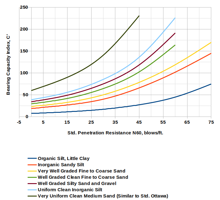
 (2)
(2)