

Comparison of Levee Underseepage Analysis Methods Using Blanket Theory and Finite Element Analysis
Thomas L. Brandon, Abeera Batool, Martha Jimenez, Noah D. Vroman, and Maureen K. Corcoran
U.S. Army Corps of Engineers, Engineer Research and Development Centre
ERDC/GSL TR-18-24
August 2018
This report provides a comparison of levee underseepage analysis methods using Blanket Theory and finite element analysis. Blanket Theory is a set of closed-form solutions for computing seepage pressures and flows beneath levees. These solutions were introduced in a U.S. Army Corps of Engineers (USACE) 1956 technical manual and are also shown in the 2000 version of USACE Engineer Manual, “Design and Construction of Levees.” Derivations of Blanket Theory, which have not been previously documented, are thoroughly documented in this report. These derivations include the standard seven Blanket Theory cases and provide the key assumptions necessary for the accuracy of the solution; they highlight the errors in the Blanket Theory equations shown in the 2000 USACE engineering manual. An additional Blanket Theory case, which include a cut-off wall located beneath the levee, is derived in this report. Subsequently, an evaluation of the Blanket Theory solutions is made using finite element analysis. This evaluation included the standard seven Blanket Theory cases, the additional Blanket Theory case, and layered strata. This evaluation demonstrates where the analysis methods did or did not produce similar results. The finite element analysis method is further evaluated comparing different finite element analysis software. Finally, general guidelines for performing levee underseepage finite element analysis are provided in this report.
Design and Construction of Levees
U.S. Army EM 1110-2-1913
30 April 2000
The objective of this manual is to develop a guide for design and construction of levees. The manual is general in nature and not intended to supplant the judgement of the design engineer on a particular project.
The term levee as used herein is defined as an embankment whose primary purpose is to furnish flood protection from seasonal high water and which is therefore subject to water loading for periods of only a few days or weeks a year. Embankments that are subject to water loading for prolonged periods (longer than normal flood protection requirements) or permanently should be designed in accordance with earth dam criteria rather than the levee criteria given herein.
Design Guidance for Levee Underseepage
U.S. Army ETL 1110-2-569
1 May 2005
The purpose of this document is to provide interim guidance for design of levees to minimize the adverse effects of levee underseepage. This ETL recommends exit gradients and associated minimum acceptable factors of safety. Use of this guidance should minimize emergence of adverse levee underseepage and initiation of sand boils along flood-control levees with a landside top stratum. EM 1110-2-1913, Design and Construction of Levees, currently contains design recommendations for levee seepage control. Except for the changes recommended in this ETL, all other definitions, design equations and procedures recommended in EM 1110-2-1913 should be followed. Where changes are recommended, the specific EM reference is noted in brackets. Currently, EM 1110-2-1913 is in the process of being updated to incorporate these recommendations and other changes. This ETL will be rescinded when the EM is revised.
Evaluation of I-Walls
U.S. Army ETL 1110-2-575
1 September 2011
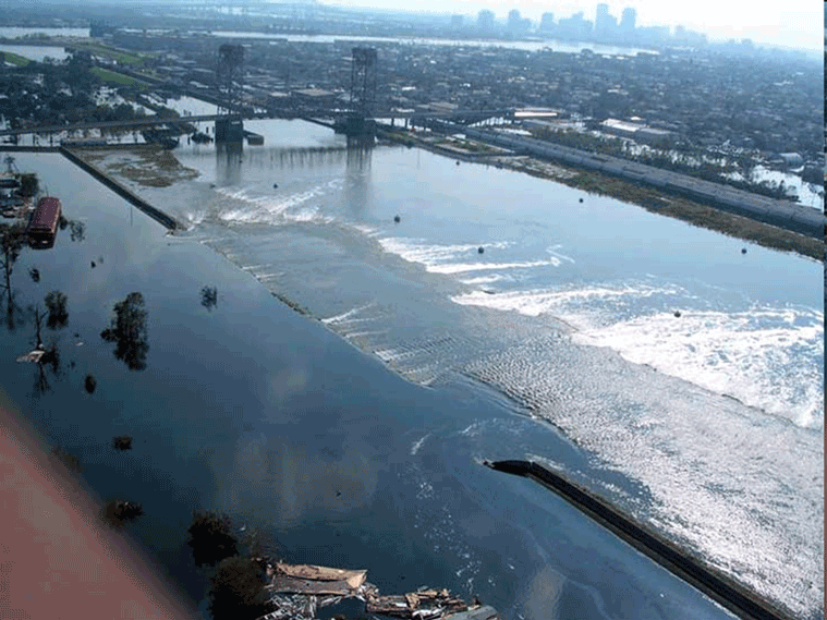
This Engineer Technical Letter (ETL) provides updated technical criteria and guidance for evaluation of existing I-walls. General guidance for performing I-wall evaluation is provided along with detailed updates to existing guidance that focus on three I-wall performance items: the flood-side gap that was discovered at I-walls in New Orleans after Hurricane Katrina; the rotational stability failure mode found to be the critical failure mode for most I-walls evaluated nationwide in the Phase II evaluation; and criteria for consideration of deflections. This guidance is for I-walls designed to provide flood risk reduction from inland flooding, not from coastal storm surges with significant wave and vessel impact loads. I-walls in coastal areas shall be evaluated in consultation with the Headquarters, U.S. Army Corps of Engineers.
Retaining and Flood Walls
U.S. Army EM 1110-2-2502
29 September 1989
This manual provides guidance for the safe design and economical construction of retaining and flood walls. This manual is intended primarily for retaining walls which will be subjected to hydraulic loadings such as flowing water, submergence, wave action, and spray, exposure to chemically contaminated atmosphere, and/or severe climatic conditions. For the design of retaining walls which will not be subjected to hydraulic loadings or severe environmental conditions as described above, TM 5-818-1 may be used for computing the loadings and evaluating the stability of the structure.
The Seismic Design of Waterfront Retaining Structures
Note: in addition to a complete description of seismic design aspects of retaining walls, this report has one of the best public domain description of lateral earth pressures available.
Robert M. Ebeling and Ernest E. Morrison, Jr.
USAE Waterways Experiment Station Information Technology Laboratory Technical Report ITL-92-11
Naval Civil Engineering Laboratory NCEL TR-939
This technical report deals with the soil mechanics aspects of the design of waterfront retaining structures built to withstand the effects of earthquake loadings. It addresses the stability and movement of gravity retaining walls and anchored sheet pile walls, and the dynamic forces against the walls of drydocks and U-frame locks.
The effects of wall displacements, submergence, liquefaction potential, and excess pore water pressures, as well as inertial and hydrodynamic forces, are incorporated in the design procedures. Several new computational procedures are described in this report. The procedures used to calculate the dynamic earth pressures acting on retaining structures consider the magnitude of wall displacements.
For example, dynamic active earth pressures are computed for walls that retain yielding backfills, i.e., backfills that undergo sufficient displacements during seismic events to mobilize fully the shear resistance of the soil. For smaller wall movements , the shear resistance of the soil is not fully mobilized and the dynamic earth pressures acting on those walls are greater because the soil comprising the backfill does not yield, i.e., a nonyielding backfill.
Procedures for incorporating the effects of submergence within the earth pressure computations, including consideration of excess pore water pressures, are described.
