
Because of the wide variety of topics relating to retaining walls, there are several pages and topics. This page has more general documents; more specific topics are covered in the following pages:
- Anchorage, Tieback and Underpinning Systems
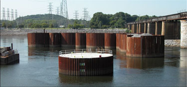
- Levees and Marine Retaining Walls
- Mechanically Stabilised Earth (MSE) Walls and Reinforced Soil Slopes
- Sheet Piling (it has moved to our companion site, click here for the link)
- Soil Nailing
Backfill for Subsurface Structures
UFC 3-220-04FA
16 January 2004
Supercedes:
U.S. Army TM 5-818-4, June 1983 (also available)
This manual is for the guidance of designers, specification writers, and especially field personnel engaged in designing, planning, and conducting earthwork operations around major deep-seated or subsurface structures.
The greatest deficiencies in earthwork operations around deep-seated or subsurface structures occur because of improper backfilling procedures and inadequate construction control during this phase of the work. Therefore, primary emphasis in this manual is on backfilling procedures. Design and planning considerations, evaluation and selection of materials, and other phases of earthwork construction are discussed where pertinent to successful backfill operations.
Although the information in this manual is primarily applicable to backfilling around large and important deep-seated or buried structures, it is also applicable in varying degrees to backfilling operations around all structures, including conduits.
Determination Of Earth Pressure Distributions For Large-Scale Retention Structures
J. David Rogers, Ph.D., P.E., R.G.
University of Missouri-Rolla
Various earth pressure theories assume that soils are homogeneous, isotropic and horizontally inclined. These assumptions lead to hydrostatic or triangular pressure distributions when calculating the lateral earth pressures being exerted against a vertical plane. Field measurements on deep retained excavations have shown that the average earth pressure load is approximately uniform with depth with small reductions at the top and bottom of the excavation. This type of distribution was first suggested by Terzaghi (1943) on the basis of empirical data collected on the Berlin Subway and Chicago Subway projects between 1936-42. Since that time, it has been shown that this uniform distribution only occurs when the following conditions are met:
- The upper portions of the vertical side walls of the excavation are supported in stages as the excavation is deepened;
- The walls of the excavation are pervious enough so that water pressure does not build up behind them; and
- The lateral movements of the walls are kept below 1% to 2% of the depth of the excavation.
With the passage of time, the approximately uniform pressure distribution evidenced during construction has been observed to transition toward the more traditional triangular distribution. In addition, it has been found that the tie-back force in anchored bulkhead walls generally increases with time. The actual load imposed on a semi-vertical retaining wall is dependent on eight aspects of its construction:
- The degree of saturation of the wall backfill in the zone of active or at-rest earth pressure.
- The degree of relative compaction of the wall backfill within the active or at-rest envelopes.
- The structural stiffness of the retaining wall system and its ability to deflect outward in response to “active” earth loads.
- The magnitude and inclination of thrust generated by soil loads due to either inclined bedding, filling, or finished grades behind the wall.
- The inclination between the wall itself and the backfill materials.
- The applicable skin friction at the wall/backfill interface.
- The vertical and horizontal components of loads associated with structural tie-backs.
- Live or dead surcharge loads above and/or behind the wall.
Each of these factors should be considered and appropriately evaluated separately. The final earth pressure calculations can then be made which will incorporate the design life of the wall and the environmental extremes to which the wall will be subjected (such as likely fluctuations in the groundwater table or freezing ground, etc.).
Development of an Earth Pressure Model for Design of Earth Retaining Structures in Piedmont Soil
J. B. Anderson and V. O. Ogunro
University of North Carolina at Charlotte College of Engineering
FHWA/NC/2006-51
October 2008
Anecdotal evidence suggests that earth pressure in Piedmont residual soils is typically over estimated. Such estimates of earth pressure impact the design of earth retaining structures used on highway projects. Thus, the development of an appropriate model for estimating earth pressure would result in more rational design of retaining structures in Piedmont residual soils. Accordingly, the objective of this research was to develop an earth pressure model for Piedmont residual soil. An experimental program to estimate, model, and measure earth pressure in Piedmont residual soils was carried out by the University of North Carolina at Charlotte. This study centred around the instrumentation, construction, and load testing of four sheet pile retaining walls at two sites in the Charlotte Belt and Carolina Slate belt regions of the Piedmont. The scope of work included extensive in situ and laboratory soil testing to estimate soil strength parameters for the residual soils; and numerical models to plan the load testing program and evaluate the results. Results of the load tests showed little or no earth pressure due to Piedmont residual soil. Interpretation of data from the sites using theoretical and numerical methods supports this findings. Conclusions from this study include:
- The earth pressure currently used in design of retaining structures in Piedmont soils is greater than earth pressure measured during load tests. Field measurements from the instrumented wall load tests demonstrated that the retained soils exerted little or no pressure on the structure.
- The Piedmont soils that were tested in this research had significant strength. The average drained friction angle was 28 degrees and the average drained cohesion intercept was above 300 psf. These values were consistent with those found in the literature for similar soils.
- Based on the soil test results as well as the minimal earth pressure detected during the load tests, the soil strength parameters, φ’ and c’ should be used together in Rankine’s earth pressure equation to predict the earth pressure in Piedmont soils.
- Triaxial tests provided the most consistent measurement of φ’ and c’. The borehole shear tests also measure φ and c’ but should only be used when triaxial testing is unavailable.
Relationships between Basic Soils-Engineering Equations and Basic Ground-Water Flow Equations
Donald G. Jorgensen
U.S. Department of the Interior
Geological Survey Water-Supply Paper 2064
1980
The many varied though related terms developed by ground-water hydrologists and by soils engineers are useful to each discipline, but their differences in terminology hinder the use of related information in interdisciplinary studies. Equations for the Terzaghi theory of consolidation and equations for ground-water flow are identical under specific conditions. A combination of the two sets of equations relates porosity to void ratio and relates the modulus of elasticity to the coefficient of compressibility, coefficient of volume compressibility, compression index, coefficient of consolidation, specific storage, and ultimate compaction. Also, transient ground-water flow is related to coefficient of consolidation, rate of soil compaction, and hydraulic conductivity. Examples show that soils engineering data and concepts are useful to solution of problems in ground-water hydrology.
Rockery Design And Construction Guidelines
Darren A. Mack, P.E., Steven H. Sanders, P.E., William L. Millhone, P.E., Renée L. Fippin, P.E., and Drew G. Kennedy, P.G.
FHWA-CFL/TD-06-006
November 2006
Rockeries consist of earth retaining and/or protection structures comprised of interlocking, dry-stacked rocks without mortar or steel reinforcement. They have been used for thousands of years and rely on the weight, size, and shape of individual rocks to provide overall stability. Some of the earliest rockeries constructed by the Federal Government date back to 1918. Within the private sector, commercially built rockeries have been constructed in the Pacific Northwest for at least the last four decades and in Northern California and Nevada for at least the last 10 years. As rockery design procedures tend to vary regionally, studies were performed to determine the methods by which rockeries are designed and constructed in various regions throughout the western United States. These design methods were then compared using several typical rockery design loading conditions to determine how the resulting rockery designs differ and which methods are most appropriate for a proposed design for the FHWA’s FLH Divisions. Based on the research performed, a rational design methodology, which evaluates rockery stability as a function of the rockery geometry (height, base width, and batter), rock properties and placement, and lateral pressure imposed by the backfill materials, was developed. A sample design problem is included. Recommendations for specifying and constructing rockeries that are consistent with the design methodology are also provided.
Seismic Analysis of Cantilever Retaining Walls, Phase I
Russell A. Green and Robert M. Ebeling
Information Technology Laboratory
U.S. Army Engineer Research and Development Center
ERDC/ITL TR-02-3
September 2002
This report presents the results of the first phase of a research investigation into the seismic response of earth retaining structures and the extension of the displacement controlled design procedure, as applied to the global stability assessment of Corps retaining structures, to issues pertaining to their internal stability. It is intended to provide detailed information leading to refinement of the Ebeling and Morrison (1992) simplified seismic engineering procedure for Corps retaining structures. Specific items addressed in this Phase 1 report deal with the seismic loads acting on the stem portion of cantilever retaining walls. It is envisioned that this information will be used in the development of a refined engineering procedure of the stem and base reinforced concrete cantilever wall structural members for seismic structural design.
Seismic Structural Considerations for the Stem and Base of Retaining Walls Subjected to Earthquake Ground Motions
Ralph W. Strom and Robert M. Ebeling
U.S. Army Corps of Engineers ERDC/ITL TR-05-3
May 2005
Cantilever retaining walls can respond externally to earthquake ground motions by sliding or by rotating, or internally by stem wall yielding. The type of response that will have the greatest impact on post-earthquake performance will likely depend on restraint conditions at the base of the wall. Walls founded on soil without an invert slab are most likely to dissipate the inertial energy imposed by earthquake ground motions by sliding. This may also be true for walls founded on fissured or fractured rock. Walls founded on soil or on fissured or fractured rock and prevented by an invert slab from moving laterally are more likely to tip (i.e., rotate) than to slide during a major earthquake event. Walls founded on competent rock without significant joints, faults, or bedding planes and prevented by a strong bond at the rock-footing interface from either translating or rotating are likely to dissipate energy through plastic yielding in the stem wall. All three responses can leave the retaining wall in a permanently displaced condition.
The purpose of this report is to provide methodologies for conducting a performance-based earthquake evaluation related to plastic yielding in the stem wall. The methodologies include evaluation of brittle or force-controlled actions and the evaluation of ductile or deformation-controlled actions. The later evaluation provides estimates of permanent (residual) displacement for walls dominated by a stem wall yielding response.
Performance-based evaluation methodologies are demonstrated with respect to a wall designed to current Corps ultimate strength design criteria and with respect to an older retaining wall designed to working stress design criteria. Lap splice deficiencies related to older walls are discussed and performance-based evaluation techniques proposed. At present the Corps computer program CWRotate is able to estimate permanent displacements associated with a sliding response and a rotational response. An enhancement is proposed to provide estimates of permanent (residual) displacement for walls dominated by stem wall yielding.
Trenching and Shoring Manual
California Department of Transportation
Revision 1, August 2011
Unfortunately, CALTRANS has changed the terms and conditions surrounding redistribution of this document. Revision 2 of this document can be found at this location.
We also have the January 2000 (Revision 12) version of this manual here.
The California Department of Transportation Trenching & Shoring Manual was originally developed by the Offices of Structure Construction in 1977. Its purpose then, which continues now, is to provide technical guidance for Structure’s field engineers analyzing designs of trenching & shoring systems used in the California Highway Construction program. Beginning with the initial edition of 1977, this Manual was well received by both the Department and the construction industry, and was distributed nationwide as well as to many foreign countries.
This 2011 Manual edition remains to be devoted to the analysis of trench and excavation earth support (shoring) systems needed for the construction of the Department’s infrastructure. Its main objectives are to inform the Engineer of California’s legal requirements, and to provide updated technical guidance for analysis and review. The Engineer should bear in mind that this Manual is a book of reference and instruction to be used with respect to the administration and engineering of excavation shoring. In cases of conflict, the contract documents shall prevail. This edition includes significant procedural analysis improvements that have been developed since the previous major update of 1990.
These enhancements were possible through significant contribution from Anoosh Shamsabadi PhD, PE. His work and those of Kenneth J Burkle, PE represent thousands of hours of effort for this Manual and for the current Caltrans Trenching and Shoring Check Program.
Current concepts in soil mechanics or geotechnical engineering are summarized in order to better acquaint the reader with the practical considerations and accepted application of theoretical principles. Some situations or conditions that may cause difficulty are noted. This 2011 Edition has reorganized and consolidated some Chapters of the previous Manual. A significant change is the chapter on Earth Pressure Theory, which was developed around AASHTO and Transportation Research Board (TRB Report 611) equations. The new AASHTO simplified procedures now provides the ability to address conditions with multiple soil layers, both granular and cohesive.
