
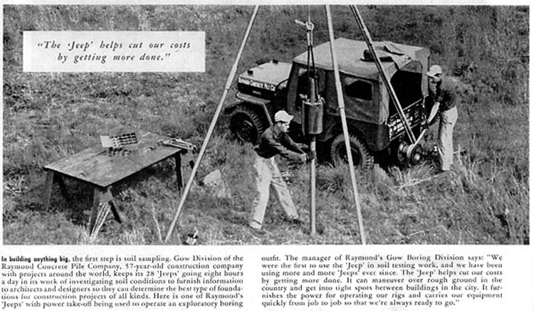
Above: Raymond Concrete Pile Company’s Gow Division’s SPT rig is featured in a Willys Overland advertisement for the Jeep during the 1950’s.
Application of Geophysical Methods to Highway Related Problems
W. Ed Wightman, Frank Jalinoos, Philip Sirles and Kanaan Hanna
FHWA Contract DTFH68-02-P-00083
September 2003
This document is designed to provide highway engineers with a basic knowledge of geophysics and nondestructive test (NDT) methods for solving specific transportation related problems. The document is not intended to make engineers experts in the field of geophysics, but rather to provide them with tools that will assist them in the use of suitable geophysical and NDT techniques to evaluate problems for design, planning, construction, or remediation efforts.
A table is included to provide the user with a simplified approach of suggested method(s) for various highway engineering problems. In this document, the term NDT is used to refer to condition evaluation of engineered structures. Condition evaluation includes integrity assessment for defects and corrosion, and the determination of unknown geometry, such as unknown foundation depths or extent of foundations. A broad range of practical methods are presented, including most traditional geophysical methods. These have been adapted to provide solutions more specific to a variety of engineering problems.
The document is divided into two parts. The first part is problem oriented and provides a range of geophysical imaging and NDT methods that can be used to solve particular highway-related problems. The second part provides more comprehensive discussions of the geophysical methods and theory.
Soil and Rock Logging, Classification, and Presentation Manual
California Department of Transportation (CALTRANS)
2010
Detailed soil and rock descriptions are an essential part of the information developed to support Caltrans’ design and construction processes. Subsurface information for any given area is, and can be, generated and accumulated over a prolonged period of time by various geotechnical practitioners for different projects and purposes. It is imperative that geotechnical practitioners working on Caltrans projects use standardized terminology and procedures to maintain consistency in borehole logging and reporting practices. Geotechnical Services in the Division of Engineering Services has published this Manual to ensure the Department’s investment in maintaining consistent logging practices.
This Manual, “Soil and Rock Logging, Classification, and Presentation Manual”, addresses the
following:
- Serves as a comprehensive reference for Departmental staff, consultants, and contractors
- Provides standardized soil description and identification procedures utilizing field data
- Provides standardized soil classification procedures utilizing laboratory data
- Provides standardized rock description and identification procedures utilizing field and laboratory data
- Serves as a basis for Departmental products and tools, such as:
- Boring Log presentation formats,
- Log of Test Borings (LOTB) legend sheets,
- Descriptive terminology presented in geotechnical reports, and
- Geotechnical Data Management System
The information presented in this Manual is based predominantly on American Society for Testing and Materials (ASTM) standards and other publications. These references provide standardized methods for identifying, describing, or classifying soil and rock; however, they do not provide adequate descriptive terminology and criteria for identifying soil and rock for engineering purposes. Consequently, this manual extends, and in some cases modifies these
standards to include additional descriptive terms and criteria.
In addition to soil and rock identification, description, or classification, this Manual contains instructions that present Departmental standards for borehole and sample identification, minimum material requirements for various laboratory tests, and boring log presentation formats.
Development of a Free-Field Soil Stress Gage for Static and Dynamic Testing
J.K. Ingram
U.S. Army Corps of Engineers Technical Report I-814
February 1968
This report describes the development of three free-field soil stress gauge types. One gauge design, the sand dollar gauge, was abandoned early in the investigation, while the other two, the W and SE gauges, were subjected to various evaluation tests. Static and dynamic tests in sand and clay were conducted in the Waterways Experiment Station’s Small Blast Load Generator (SBLG) at depths of burial up to 2-1/2 feet. The test soils and gauge placement techniques used in the SBLG tests are described in Appendix B. The gauges have been used in the laboratory evaluation of a cold gas loader and in two field tests: Operation Snowball, and a small energy-coupling-efficiency test conducted in 1965. Evaluation of the performance of the gauges in these tests is presented in Appendix A. The gauges are rugged and relatively easy to place in the laboratory. They may be used for both static and dynamic measurements and have a linear pressure range from I to above 1,800 psi. The gauges have very low acceleration sensitivity and hysteresis, and have excellent dynamic response capability–rise time less than g(r-c and undamped natural frequency greater than 40 kHz. The temperature sensitivity (zero shift) of the gauges is such that it will be of little consequence in dynamic tests and can be corrected for in long-term static tests. Electrical sensitivity (as opposed to zero shift) remains essentially constant from -30 to 150 F. Of the two gauge types discussed, the SE gauge is recommended for use. It is much easier to place, is more rugged, and produces a cleaner dynamic signal than the W gauge The gauges can be calibrated to compensate for registration errors due to differences in soil and gauge modulus; however, gauge registration was found to be a function of placement method, depth of burial, input pressure, and conditions of the medium, not simply of modulus ratio. Where a minimum number of gauges are to be used in sand, a dense tamping-in placement method is recommended for general use in laboratory tests. For tests in clay, the cut/nocover method, in which the gage is placed in a matched cavity flush with the clay surface and covered in normal lifts, is recommended. Further investigation of field placement techniques is recommended.
Dutch Friction-Cone Penetrometer Exploration of Research Area at Field 5, Eglin AFB, Florida
John H. Schmertmann
U.S. Army Corps of Engineers Contract Report S-69-4
October 1969
This is a report on the results of an investigation of the homogeneity of soil conditions at a research site within Eglin AFB, S Florida. Twenty cone soundings, using a static, Dutch friction cone penetrometer, reached an average depth of 70 ft, varying from 62 to 102 ft. The field work was accomplished in four working days. The load on the penetrometer was automatically recorded for 11 of these soundings, permitting greater precision in the determination of the ratio of soil friction against the cone friction jacket to the bearing capacity of the cone point. All mechanical equipment .appeared to operate in an excellent manner. No evidence was found to indicate significant thicknesses of cohesive soil layers. Friction ratios were unusually uniform over the entire site investigated and fell within the range usually interpreted as indicating clean sand. There was also no evidence of perched water tables. The-cone bearing logs for the upper 20 ft of sand, a natural deposit, also indicated that it is uniform in density variation with depth over the research area investigated in detail, and the surrounding area as well. Below 20 ft there is considerable point to- point variation in sand density. However, on the average the research area and vicinity show a definite uniformity in the way in which density varies with depth, The entire site area is as homogeneous as one can expect to find in natural, coarse-grained deposits of the depth considered herein.
 Materials Testing

We also have the previous edition of this (FM 5-530) available for download here.
Field Manual FM 5-472
NAVFAC MO-330
AFJMAN 32-1221 (I)
1 July 2001 (Change 2)
This manual provides the technical information necessary for military personnel to obtain samples and perform engineering tests and calculations on soils, bituminous paving mixtures, and concrete. These tests and calculations are required to achieve proper design with these materials and adequate control over their use in military construction.
This manual covers soils, aggregates, bituminous cements, bituminous paving mixtures, Portland cement concrete, and stabilized soil including stabilizing agents such as bitumens, cements, lime, fly ash, and chemical modifiers. The manual gives detailed instructions for taking adequate representative test samples and step-by-step procedures for making physical properties tests and for recording, calculating, and evaluating the test results. The manual explains methods for designing bituminous paving mixtures and port land cement concrete and ways of stabilizing soil. It also gives the procedures and tests required to control the manufacture of these mixtures. The manual describes the tools and equipment for performing these tests and contains general instructions for the care, calibration, and use of test equipment.
A New Ground Water Survey Tool: The Combined Cone Penetrometer/Vadose Zone Vapour Probe
Susan T. Litherland, Thomas W. Hoskings and Ronald L. Boggess, McClelland Engineers
A soil cone penetrometer has been modified to allow sampling of gases in the vadose zone. This tool was developed to obtain information concerning soil type and quantitative volatile organic compound data in the unsaturated zone simultaneously. The primary uses are in identifying leaks and locating contaminant plumes from underground storage tanks and pipelines, and surveying uncontrolled waste sites to strategically place exploratory borings and ground water monitoring wells. The Cone Penetrometer/Vadose Zone Vapour (CP/VZV) probe consists of a gas collection barrel positioned 18 inches above the tip of the cone penetrometer. The tool is hydraulically advanced into the ground using a drill rig equipped with an automatic chuck assembly. Wiring from the cone penetrometer and tubing from the gas collection barrel are connected to above ground equipment. Gas samples are analysed by either an organic vapour meter or portable gas chromatograph (GC) depending upon the information desired. The cone penetrometer is used to generate immediate feedback on soil stratigraphy. Depending on the type of soils encountered, gas sampling can be continuous with depth or only in porous soils as identified by the cone penetrometer data. The CP/VZV probe significantly reduces the time and cost of the investigation of sites contaminated with volatile petroleum hydrocarbons and organic chemicals. It reduces the number of borings ultimately required by allowing more knowledgeable placement of exploratory borings and ground water monitoring wells. By reducing the number of borings its use reduces the number of soil samples which must be taken and, hence, the potential exposure of the field personnel may also be reduced.
Normalization and Prediction of Geotechnical Properties Using the Cone Penetrometer Test (CPT)
Richard S. Olsen
U.S. Army Corps of Engineers, Waterways Experiment Station
Technical Report GL-94-29
August 1994
The objectives of this research were to develop techniques for (1) stress normalization of CPT measurements (and geotechnical properties) and (2) CPT prediction of geotechnical properties using cone and sleeve friction resistance values. Stress normalization allows a variable geotechnical property to be reduced to an equivalent value at a standard confining stress.
A new concept, the Stress Focus, was identified which provides a basis for understanding soil strength as a function of confining stress. This study demonstrated that sand friction angles for different initial relative densities converge to a Stress Focus at high confining stress (approximately 100 atm), where the strength behaviour is similar to that of a sedimentary rock. Dilation of dense sands decreases with increased confining stress until the Stress Focus is reached, as confirmed using historic high pressure triaxial test data as well with CPT measurements from laboratory chamber tests and uniform soil layers. The paths of convergence to the Stress Focus are exponentially related to confining stress and are the basis for development of CPT cone and sleeve friction resistance normalization techniques. The overburden stress at the Stress Focus is soil type dependent.
The stress exponent for SPT normalization was shown to be equal to the CPT derived stress exponent.
CPT correlations to geotechnical properties were established using both CPT cone resistance and friction ratio. These correlations were based on a large database which was developed for this research effort. Statistical evaluation during the development of these correlations concentrated on excluding biased data. CPT based correlations were established for the following geotechnical properties: SPT blow count, unconsolidated undrained triaxial test strength, field vane shear test strength, and shear wave velocity.
Site Investigations
C. R. I. Clayton, M. C. Matthews and N. E. Simons
Department of Civil Engineering, University of Surrey, England
This book is a complete treatment of site investigations, including the following topics:
- Planning and Procurement
- Description and Classification of Soils and Rocks
- The desk study and walk-over survey
- Subsurface Exploration: Engineering Geophysics
- Subsurface Exploration: Boring, Drilling, Probing and Trial Pitting
- Sampling and Sample Disturbance
- Undisturbed Sampling Techniques
- Laboratory Testing
- In Situ Testing
- Basic Field Instrumentation for Site Investigation
By 1953, Terzaghi stated in connection with site investigation that ‘we have acquired all the knowledge which is needed for a rational interpretation of the observational and experimental data’. The reader may reasonably ask what is to be gained from this book, since techniques are so well established. In reality, since 1950, four main changes have taken place.
- First, many of the methods introduced before and since have been the object of criticism as a result of differences between predictions and subsequent observations.
- Secondly, a considerable number of the lessons learnt before 1950 have been forgotten: few U100 samplers in use today are of the standard required by Hvorslev (1949) for undisturbed sampling, and much fieldwork remains unsupervised by engineers.
- Thirdly, few engineers have an experience or understanding of the techniques of boring and drilling holes for site investigations, and most clients remain unaware of the importance of this part of the work.
- Finally, recent years have seen the introduction of sophisticated and expensive methods of testing and computer analysis which cannot be sensibly applied to samples and predictions of soil conditions of indeterminate quality.
This is an excellent companion to Verruijt’s Soil Mechanics book.
Soils Sampling and Testing Training Guide for Field and Laboratory Technicians on Roadway Construction
Eugene R. Russell and Michael Renk
Kansas State University
Report No. K-TRAN: KSU-96-10
December 1999
This manual has been developed as a training guide for field and laboratory technicians responsible for sampling and testing of soils used in roadway construction. It was completed in conjunction with K-TRAN Project KSU-96-10, entitled “Pilot Study to Determine Personnel Certification and Training.”
The development and implementation of Quality Control/Quality Assurance (QC/QA) specifications by the Kansas Department of Transportation has been a driving force behind the development of a soils training and certification program. Soils training and certification will increase the knowledge of laboratory, production, and field inspectors. Both the owner agency and the contractor will benefit with an increased number of qualified personnel to perform acceptance and quality control functions. In addition, it is anticipated that this program and its standardized set of core tests will help to achieve certification reciprocity throughout the region. This manual is a guide for training personnel to perform the core soils tests they should understand in order to be certified.
The manual is based on ASTM and AASHTO test methods and procedures. During the 4th Annual FHWA Region 5 & 7 Training and Certification Workshop, a core content of ASTM and AASHTO tests for soil technician training was defined by the Soils Training Development Team. This training manual implements this core content for certification of laboratory soil field inspectors.
Standard Penetration Test
ETL 1110-1-138
31 March 1988
This letter furnishes information and guidance on the conduct of the Standard Penetration Test (SPT), when its penetration values are used in soil liquefaction evaluations.
In 1958, the American Society for Testing and Materials (ASTM) first adopted the “Standard Method for Penetration Test and Spilt-Barrel Sampling of Soils, ASTM D1586 (SPT)”. The SPT has been used routinely in subsurface exploration and soil design, with many engineering relationships between SPT N values and other soil design parameters (such as relative density, angle of internal friction, shear strength, bearing capacity, and soil liquefaction potential) having been developed, However, In spite of the seemingly detailed “standard” method specified in ASTM D 1586-84, there still exist many factors which lead to a wide variation In SPT results for a given soil This variation, along with the low degree of repeatability, has caused difficulties in interpreting SPT results and using historical data with confidence. Recent research, especially In the dynamics of the SPT and the field energy measurement of the SPT hammers, have greatly advanced the knowledge of the SPT and, as a result test variations can be minimized.
Subsurface Investigations– Geotechnical Site Characterization
Note: this document has something of a complicated history behind it.
- For reasons unknown to us, there are two versions of FHWA NHI-01-031 available. The link above is the later (May 2002) version. Click here for the earlier (July 2001) version.
- The earlier version of this manual was FHWA-HI-97-021 (November 1997) and is available; click here to download that manual.
FHWA-NHI-01-031
May 2002
This manual is the reference text used for the FHWA NHI course No. 13231 on Subsurface Investigations and reflects current practice for such. The planning, execution, and interpretation of geotechnical site explorations in natural soil and rock are presented with regard to the design and construction of transportation facilities. The role of the geotechnical engineer in subsurface investigation, exploration methods, equipment types and their suitability are discussed. Various in-situ tests are presented, including cone penetration, dilatometer, pressuremeter, vane, and standard penetration. Rotary drilling and rock coring are reviewed in terms of the proper handling, transportation, and storage of soil and rock samples for laboratory testing. Geophysical wave and electromagnetic methods are covered. Laboratory index, strength, and stiffness testing are reviewed in complement to the field testing program. Geomaterial characterization requires the interpretation and correlation of engineering properties from the acquired field and lab measurements. The results are summarized in a geotechnical report with available geological, topographical, hydrological, and geotechnical data collected towards the analysis and design of earthwork structures and foundation design.
Test Quarries and Test Fills
EM 1110-2-2301
30 September 1994
This manual is intended to be a guide for use in planning the portions of the project geotechnical investigations dealing with rock source materials, the design and operation of a test quarry, and the design and conduct of a rock test fill program. This manual is not intended to be a textbook on engineering geology, blasting or rock excavation, or the many possible variations and elements of a test fill program. Actual investigations, test quarry design and development, and test-fill specifics must, in all instances, be tailored to individual project requirements. While the focus of the manual is upon determining the means to produce, place, and compact rock fill materials, the portions concerning test quarries are also applicable to establishing sources for other rock uses such as riprap or concrete aggregate. Part 1 of the manual will address test quarries and Part 2 will treat compacted rock test fills.
The Third Dimension of Planetary Exploration: Deep Subsurface Sampling
AIAA-2000-5301
September 2000
Strategic planning for the exploration of the Martian subsurface to search for evidence of life, sources of water, and to determine the geologic make-up and history of the planet has begun. A mission to explore and sample the Martian subsurface hydrosphere, which may be 4 km deep, will be more complex than any mission accomplished to date. In order to reduce risk a phased approach is being planned with shallow and intermediate depth precursor missions. We researchers at Los Alamos National Laboratory are conducting a conceptual system study of a 200-m intermediate-depth penetration and sampling mission on Mars. We constrained the study with a reasonable set of surface and subsurface environmental conditions and science requirements. Mission requirements include a 200-day duration, a soft lander which will fit within a Delta Ill payload fairing, a 250-kg drilling system mass limit and a maximum available energy for drilling of 1kW hr/sol. Existing and conceptual drilling technologies are compared, and the down-section process results in mechanical drilling subsystems that can be mixed to produce a number of specific systems that can be studied in more detail. Promising technology areas that need further investigation are identified.
