Roy was born September 13, 1931 in Richmond, Indiana. He grew up in Minneapolis and attended the University of Minnesota where he received B.S. and M.S. degrees in Civil Engineering. Roy then attended the University of Illinois Champaign-Urbana, where he earned his Ph.D. in Civil Engineering in 1960. Upon graduation, Roy was hired by the University of Illinois as a faculty member in their Civil Engineering Department. In 1970, he was recruited and hired by the Department of Civil Engineering at the University of Texas in Austin. Roy was an accomplished researcher and a favorite professor with the many students he taught over his 42-year career. He was instrumental in bringing national recognition to the Department of Civil Engineering at UT, which is now ranked fourth overall in the United States.
Throughout his career Roy received many awards and held leadership roles in professional societies while actively teaching and mentoring students. Some of Roy’s professional accomplishments include: the Huber Research Prize, the Croes Medal, the Norman Medal, the ASTM Hogentogler Award (twice), and his invitation to deliver the Terzaghi Lecture. In 2003, he was inducted into the National Academy of Engineering. However, to Roy, his greatest accomplishment was seeing the successes of his former students. Many have become well-respected and influential leaders in geotechnical engineering.
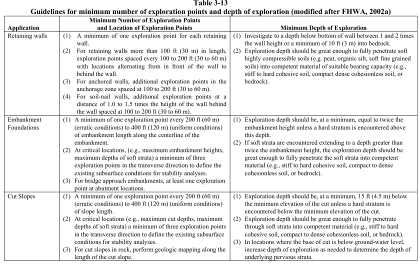
One thing that irritates me to no end is to look at a set of geotechnical plans and to realise that there is only one boring for the entire site. In a few cases that’s enough, but very few. The “uniform site conditions” of academic legend are seldom found in real life; soil conditions vary from one place to another on a site and in some stratigraphies in a matter of feet or metres. If it’s worth sending a crew out to a site for one or two borings it’s worth getting more.
The table “Guidelines for minimum number of exploration points and depth of exploration” is shown below, and is taken from the Soils and Foundations Reference Manual, which has much additional information on this and other related topics. It also deals with another issue that bedevils geotechnical exploration: going deep enough to get the information needed, especially with deep foundations. I also spent a great deal of time on this subject in my course Foundation Design and Analysis: Boring Logs and Their Interpretation, evidently more than other undergraduate courses.
One of the things that gets covered (if not very thoroughly) in Soil Mechanics is how friction is developed in soils. An analogy is made with the classic “block on a surface” problem we see in Statics, but the tie-in isn’t as strong as one would like.
The fact is that, for purely cohesionless soils, the friction between the particles and the friction between the surface and the block is basically the same Coulombic friction. As is usually the case in soil mechanics, how that actually plays out in soil properties has many complexities, but then again surface friction isn’t a simple or straightforward property in and of itself.
Another part of the problem is that, in Statics, friction isn’t taught with geotechnical considerations in mind, especially these days. This is a pity, not only for those of us in the geotechnical community but for those who work with granular materials on a production or use basis.
This is a brief treatment of the subject, basing the development of the topic from that in Movnin and Izrayelit (1970), which comes closer to relating the two quantities we see to define friction: the friction angle and the friction coefficient.
The Basics of the Friction Coefficient and Angle
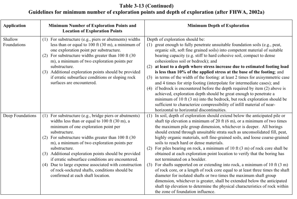
Surface friction comes from the rubbing of two surfaces together, as shown at the right. We see the three forces with which the two surfaces interact: the normal force N, the resulting friction force F and the resultant of the two R. We also see that the addition of lubricant is important in that it separates the two surfaces and reduces the effect of the asperities on each other, something that contractor and engineer alike frequently overlook in both the maintenance and performance evaluation of the equipment.
The normal and frictional forces resisting the relative motion of the two surfaces is related by the equation
F = fN (1)
With granular materials, the main difference is that the surfaces of the particles aren’t straight at all but they do rub up against each other, the asperities on the particle surface contributing to the mutual resistance of the particles. Although water acts to a limited extent as a lubricant, its largest effect is the buoyant effect on the intergranular (effective) stress, as shown below.
Returning to the first diagram, without any mutual pressure of the surfaces (the normal force N) there is no friction force F tangential to the surface. Again in soil mechanics purely cohesionless (granular) soils have no frictional strength unless weight or other pressure is applied to them.
Diagram of forces on a body on a plane surface with friction, from Movnin and Izraelyt (1970)
Now let us consider the diagram at the right. The normal force N exerted by the surface on the block (caused by the force exerted on the block Q) and the frictional force F (caused by the force P which attempts to move the block) add vectorially to a resultant R, which in turn has an angle with the normal force N. The geometry of the forces and Equation (1) relate the angle to the friction factor as
f = F/N = tan (φ) (2)
Cone of Friction
Although F and N are related through both Equations (1) and (2), in reality F cannot exist without some tangential force pushing the block. This is the force P which is attempting to push the block along the plane. As P increases F increases until we get to a point where we have impending motion, beyond which the block moves and begins to accelerate. The value of f or φ when impending motion turns into actual motion is when we reach the ultimate value of f or φ, which we will designate as f0 or φ0.
Cone of Friction, from Movnin and Izraelyt (1970)
These form a “cone of friction.” This cone of friction can be seen in the diagram at the left. As long as F < f0 N (or F < tan (φ0) N) and the resultant Q of N and F is within the cone, the block is motionless. Beyond that point it moves, and the coefficient of friction in motion can be different (usually smaller) than the coefficient of friction at the point of impending motion.
It is here that we can relate the friction factor f and the angle of friction φ can be related to each other and to concepts familiar to geotechnical people. When we construct the Mohr-Coulomb diagram, we define a failure envelope of legal stress states (within the envelope) and illegal stress states (outside the envelope.) We can see all of these with the failure function below. When the failure function is negative (1), we are within the envelope and failure does not take place. When the failure function is zero (2), we have impending failure. When the failure function is positive (3), we have failure and an illegal stress state.
Three-dimensional envelopes are certainly common in geotechnics, especially in finite elements. An example of this is shown below.
Determining the Friction Factor or Angle
Determining the angle of friction, from Movnin and Izraelit (1970)
To determine the friction angle, one simple way is to start with a block and a level surface and then raise the angle of the surface until the block moves. Such an apparatus is shown at the left.
As the angle α increases the direction of the weight G relative to the surface changes in can be divided into two parts: the normal force G2 and the tangential force G1. The latter will move the block down but it is resisted by the friction force F, which will resist until G1 > F0, at which point the block will start to move down the slope at a constant acceleration. By noting the angle at which this takes place, both f0 or φ0 = α0 can be determined. The math for this is similar to the level surface and block.
The geotechnical counterpart to this is the angle of repose. Suppose we allow a small stream of sand to drop on a surface. Over time the sand will build up into a conical pile with the surface at an angle to the flat surface the sand is streamed onto. This angle is referred to as the angle of repose. In theory the angle of repose is equal to the friction angle of the soil, although with the usual complexities of geotechnics this isn’t always the case. There are clean sands with which we can use the angle of repose to estimate the internal friction angle of the soil. When I was teaching at UTC, some of the students were working on the ASCE MSE Wall project and needed a friction value for the sand being used in the box. While they were looking at direct shear or triaxial testing, I suggested using the angle of repose to get a “ballpark” value. They did this and it was helpful.
Some Comments
The use of the angle of friction has fallen out of favour in engineering education, which is one reason why it is difficult to relate friction as taught in Statics to friction as used in geotechnical engineering. That wasn’t always the case; one example from the early twentieth century is Tapered Keys and Their Use In Vulcan Hammers.
Hopefully this treatment of the subject will be useful to students to help them relate the concept of friction in statics to that in geotechnical engineering.
A couple of years ago our bookstore was reorganised to put our offerings in wider distribution. Some of the discontinued titles are being put back into print, directly from the printer. Click on the title or image to to order.
This manual presents guidelines for calculation of the bearing capacity of soil under shallow and deep foundations supporting various types of structures and embankments. Principles for evaluating bearing capacity presented in this manual are applicable to numerous types of structures such as buildings and houses, towers and storage tanks, fills, embankments and dams. These guidelines may be helpful in determining soils that will lead to bearing capacity failure or excessive settlements for given foundations and loads. Consideration should be given to obtaining the services and advice of specialists and consultants in foundation design where foundation conditions are unusual or critical or structures are economically significant.
Settlement Analysis
This manual presents guidelines for calculation of vertical displacements and settlement of soil under shallow foundations (mats and footings) supporting various types of structures and under embankments. Vertical displacements and settlement caused by change in stress and water content are described in this manual. Limitations of these movements required for different structures are also described. Various types of settlement are discussed in detail, including settlement due to elastic deformation, consolidation, secondary compression and creep, settlement due to dynamic loads, and expansive and collapsible soils. Solutions to soil movement problems are discussed and detailed. Deep foundations and landfills are also discussed.
This book presents information on the design of retaining walls and inland and coastal flood walls. Retaining walls are defined as any wall that restrains material to maintain a difference in elevation.
A floodwall is defined as any wall having as its principal function the prevention of loading of adjacent land. Not specifically covered in this book are seawalls which are defined as structures separating land and water areas, primarily designed to prevent erosion and other damage due to wave action. They are frequently built at the edge of the water, but can be built inland to withstand periods of high water.
Seawalls are generally characterized by a massive cross section and a seaward face shaped to dissipate wave energy. Coastal flood walls, however, are generally located landward of the normal high water line so that they are inundated only by hurricane or other surge tide and have the smooth-faced cantilever stems shown in this book. This book also describes procedures for the design of retaining and flood walls on shallow foundations, i.e., those bearing directly on rock or soil.
This book deals with the soil mechanics aspects of the design of waterfront retaining structures built to withstand the effects of earthquake loadings. It addresses the stability and movement of gravity retaining walls and anchored sheet pile walls, and the dynamic forces against the walls of drydocks and U-frame locks. It also contains one of the most complete descriptions of lateral earth pressure theory available anywhere.
The effects of wall displacements, submergence, liquefaction potential, and excess pore water pressures, as well as inertial and hydrodynamic forces, are incorporated in the design procedures. Several new computational procedures are described in this report.
The procedures used to calculate the dynamic earth pressures acting on retaining structures consider the magnitude of wall displacements. For example, dynamic active earth pressures are computed for walls that retain yielding backfills, i.e., backfills that undergo sufficient displacements during seismic events to mobilize fully the shear resistance of the soil. For smaller wall movements, the shear resistance of the soil is not fully mobilized and the dynamic earth pressures acting on those walls are greater because the soil comprising the backfill does not yield, i.e., a nonyielding backfill. Procedures for incorporating the effects of submergence within the earth pressure computations, including consideration of excess pore water pressures, are described.
Originally written to supply engineer officers and noncommissioned officers with doctrinal tenets and technical facts concerning the use and management of soils during military construction, Military Soils Engineering is one of the most practical guides to basic engineering geology and soil mechanics available. It provides guidance in evaluating soil conditions, predicting soil behavior under varying conditions, and solving soil problems principally related to military operations but applicable to the construction of a wide variety of foundations and earth structures.
Construction in a military theater of operations is normally limited to roads, airfields, and structures. This manual emphasizes the soils engineering aspects of road and airfield construction. The references included in the manual give detailed information on other soils engineering topics that are discussed in general terms.
In addition to this, the manual:
Provides a discussion of the formation and characteristics of soil and the Unified System of soil classification, used by the United States (US) Army and most geotechnical engineers;
Gives an overview of classification systems used by AASHTO and the Department of Agriculture;
Describes the compaction of soils and quality control, settlement and shearing resistance of soils;
Describes the movement of water through soils, frost action, and the bearing capacity of soils that serve as foundations, slopes, embankments, dikes, dams, and earth-retaining structures; and
Has a detailed description of the geologic factors that affect the properties and occurrences of natural mineral/soil construction materials used to build a wide variety of structures.
Military Soils Engineering is an indispensable reference for geotechnical engineers, engineering geologists and laboratory and field technicians.
This is a combination of two authoritative documents on this vital subject.
Federal Guidelines for Dam Safety (FEMA 93): These guidelines apply to management practices for dam safety of all Federal agencies responsible for the planning, design, construction, operation, or regulation of dams. They are not intended as guidelines or standards for the technology of dams. The basic principles of the guidelines apply to all dams. However, reasonable judgments need to be made in their application commensurate with each dam’s size, complexity, and hazard. Federal agencies have a good record and generally sound practices on dam safety. These guidelines are intended to promote management control of dam safety and a common approach to dam safety practices by all the agencies. Although the guidelines are intended for and applicable to all agencies, it is recognized that the methods of the degree of application will vary depending on the agency mission and functions.
Safety of Dams—Policy and Procedures (U.S. Army Corps of Engineers ER 1110-2-1156): This regulation prescribes the guiding principles, policy, organization, responsibilities, and procedures for implementation of risk- informed dam safety program activities and a dam safety portfolio risk management process within the United States Army, Corps of Engineers (USACE). Risk is defined as a measure of the probability and severity of undesirable consequences or outcome. The purpose and intent of this regulation is to ensure that responsible officials at all levels within the Corps of Engineers implement and maintain a strong dam safety program in compliance with “Federal Guidelines for Dam Safety.” The program ensures that all dams and appurtenant structures are designed, constructed, and operated safely and effectively under all conditions, based on the following dam safety and dam safety program purposes, as adopted by the Interagency Committee on Dam Safety (ICODS).