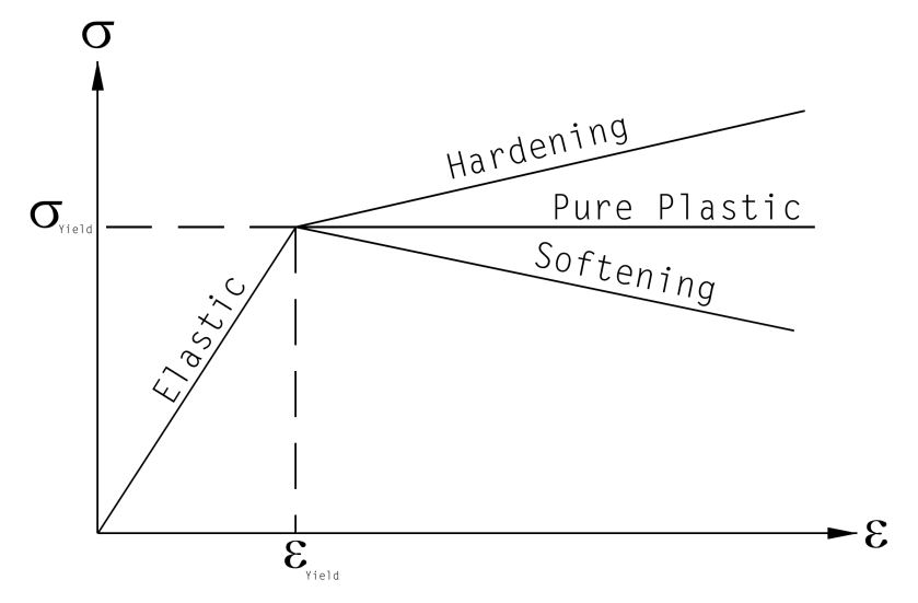
With the Mohr-Coulomb failure criterion defined, the elasto-plastic constitutive matrix can be developed. Since pure plasticity is assumed, thus once failure is reached and F=0 , the stresses can “rearrange” themselves to remain at the failure surface but cannot move from it unless the strains are reduced to the point where the stress state is within the failure surface and F<0. This is easier to see if we look at the diagram above. We should also note that, for this presentation, the plane strain/axisymmetric case will be considered; the derivation would proceed a little differently for other cases such as plane stress or three-dimensional stress.
To do this, both Equations 8 and 10 from the previous post are differentiated. Considering that
(1)
for the two-dimensional model, then
(2)
(3)
and
(4)
Inspection of Equation 3 will show that C2 and C3 are undefined for values of θ =30°. This is the well known “corner” problem which has occupied the literature for many years, as summarized by Abbo et.al. (2011). For this study the “corner cutting” of Owen and Hinton (1980) is used, and
(5)
Although the accuracy of this “corner cutting” can be improved with methods such as those of Abbo et.al. (2011), they come at more computational expense.
In like fashion for the plastic potential function,
(6)
where
(7)
and by extension
(8)
and the vectors a1 , a2 , a3 are the same as with Equation 2.
At this point we need to pause and consider how we plan to present our result. It’s certain possible, for example, to multiply through Equations 2, 3, and 4 and use this result in subsequent derivations. This approach suffers from two problems: the element expressions in the matrices and vectors become very complicated, and the computation cost is increased by the repetitive calculations. For some good advice on this subject–for this and other problems–we would suggest that you review this.
Now the elasto-plastic constitutive matrix can be considered. Here the difference between path indepedence and path dependence becomes significant. In the elastic case, we can use the elastic consitutive matrix De and, knowing the strains, compute the stresses, and perform the inverse as well. With plasticity, it is necessary to compute the strains and stresses incrementally, moving from one stress and strain state to the next and adding the results to what has gone before. We do this with both elastic, plastic and combined strains and stresses for computational consistency. The elastic results will be the same except for the additional accumulation of numerical error due to the larger number of computations.
For any strain increment partially or totally beyond the yield surface, that strain increment will contain both elastic and plastic portions (Griffiths and Willson (1986)), or
Strain increments occur normal to the plastic potential surface, thus
(10)
For elastic materials, the incremental stress-strain relationship is simply
(11)
where, for plane strain and axisymmetric problems, as before,
(12)
and also, for axisymmetric problems only,
(13)
For a perfectly elasto-plastic material, i.e., one without hardening or softening, stress changes will take place only during elastic action. Thus in these cases Equations 9, 10 and 11 can be rearranged to yield
(14)
Since stresses on the failure surface can “rearrange” themselves without leaving same surface,
(15)
Combining and rearranging Equations 9 through 15 yields the following relationships:
(16)
(17)
or
(18)
where
(19)
and finally
(20)
We need to break this down for greater understanding. Let us first define
(21)
This is a scalar quantity. (Admittedly sometimes it is difficult to follow matrix equations because they combine scalar and vector/matrix quantities.) We can thus rewrite Equation 19
(22)
and Equation 20 can be likewise rewritten as
(23)
where the identity matrix.
If plasticity has not yet been initiated, the quantity (which is a 4 x 4 matrix) is null, and the elasticity matrix governs. Once it is initiated the magnitude of
begins to increase and Dep begins to decrease, which indicates a ‘softening’ of the material. This is what we would expect with plasticity. The whole topic of matrix magnitude is not a straightforward one and is usually viewed in relationship to matrix norms, which are discussed in Gourdin and Boumharat (1989).
In any case
(24)
The first thing to note about Equation 20 is that, if same is used to reconstruct a tangent stiffness matrix KT in a true Newton stepping scheme, same KT will not be symmetric if φ ≠ ψ. For many engineering materials, and especially those where both of these quantities are zero, this is not an issue; the flow rule is associated, Dep is symmetric and KT will be also. “Regular” engineering materials are used for, say, the steel or concrete portions of a system, but for many geotechincal applications interest in plastic deformation of these components is limited. It is also not an issue with purely cohesive soils. For situations with cohesionless soils, this is not the case; generally φ ≫ ψ and a non-associated flow rule is necessary. This aspect will be important in many decisions regarding the structure and types of schemes used in the model. An overview of the values of the dilitancy angle ψ can be found in Warrington (2019).
Turning to the inclusion of plasticity itself, it is certainly possible to compute the plastic stresses from Equation 20, and also possible to explicitly derive Equation 19 (Griffiths and Willson (1986)). However, it is not always optimal to do so, either from the standpoint of a workable algorithm or from a computational efficiency standpoint. To compute the final stress state in a load or time step where failure takes place, some type of iteration or multiple steps are required. Potts and Zdravkovic (1999) state that there are two basic types of algorithms to accomplish this: substepping (such as Sloan (1987)) and return (Ortiz and Simo (1986)). For STADYN a return algorithm was chosen, and implemented as follows:
- For a load or time step, the estimated incremental strain was computed.
- The estimated incremental stress was computed, based on the assumption that the strains were still in the elastic region.
- The resulting incremental stresses were added to the stresses at the beginning of the step. If these were elastic, then plasticity was not considered and the incremental stresses were added to the original ones. If they were not, then the plasticity routine was invoked.
- The plasticity routine began by computing aF , aQ , F , θ and aβ.
- The plasticity constant λp was determined by a modification to Equation 16, namely
(25)
- The incremental strains in the return step were computed by the equation (see Equation 14)
(26)
- The return incremental stresses were thus
(27)
- Both of these were subtracted from the current estimated strain and stress, thus
(28)
- The current stress state was checked against the previous stress state. If the norm of the vector difference of the two stress states was within the convergence tolerance, the iteration was stopped and the computed elasto-plastic stresses and strains were accepted. If not, the cycle was repeated.
Potts and Zdravkovic (1999) criticize the return algorithms because they obtain a result based on information and computations in illegal stress space. However, overall the experience in this study is that the return algorithm worked well, with most of the convergence to the new failure surface stress state taking place in the first iteration and the rest refinement steps. A fair way of differentiating between the two is that, with substepping, one starts with the existing stress state and works one’s way to the failure surface, while the return algorithm starts by overshooting the failure surface and then coming back to it. The goal in both cases is to return to the failure surface, and in principle the result should be the same. Another way of differentiating between the two is that substepping is, with its avoidance of illegal stresses, more of an engineering type of approach to the problem, while the return algorithm is a more strictly mathematical method of arriving at a solution.

3 thoughts on “Elasto-Perfect Plasticity with Mohr-Coulomb Failure”