Posted in Deep Foundations, Geotechnical Engineering

It’s Coming: Geotechnical Analysis One Grain at a Time

In going through some papers, I noticed this one, Friction anlysis of large diameter steel cylinder penetration process using 3D-DEM, whose abstract is as follows:

Large open-ended cylinder piles have been widely used for engineering foundation of port. The penetration process of the large-diameter steel cylinder exhibit complex behaviors, which is difficult to be measured by test and reproduced in numerical models. This study presents a friction analysis of large diameter steel penetration process by using the discrete element method (DEM), which can simulate large deformation and nonlinearity well. Centrifugal model and full-scale model were developed to analyze the sliding friction of the cylinder during installation and the contact force chain of soil particles. The validity of the DEM model was examined by comparing with theoretical values and published studies. Parametric studies were carried out to study the effects of contact parameters on side friction. Simulation results showed that, unlike pile penetration, there is no obvious soil-plug effect during the penetration process of large-diameter steel cylinder. Besides, the inside friction is smaller than the outside friction for large-diameter steel cylinder. What’s more, the computational cost of full-scale model based on the upscale theory was less than the centrifugal model. There is a close relationship between the side friction and micro contact parameters, which provides a reference for the follow-up study of cylinder or pile penetration using DEM.

Friction anlysis of large diameter steel cylinder penetration process using 3D-DEM

Put into simple terms, DEM models the soil by a grain-by-grain analysis of its response to load, which in this case came from 22 m O.D. open-ended pipe piles for the Hong Kong-Zhuhai-Macau Bridge. Believe it or not, I seriously considered using something like this for the STADYN project, but was dissuaded from doing so because of complexity and stability issues. That’s probably for the best, because the program I was in encouraged a “roll your own” approach to computer code, and to be honest at my stage in life and background I wasn’t up to such a development.

One thing that helped the authors of this paper was the fact that the soils they were driving into was cohesionless, without the chemical bonding that comes with cohesive soils. It’s also interesting to note that these piles were vibrated into place; the whole subject of vibratory driving, its performance prediction and static capacity determination, is another long-running subject in this business.

Although the issues of cohesion and verification (always the fun part of geotechincal engineering) need further resolution, DEM is, in my opinion, the ultimate solution of the soil interaction question, and needs to be disseminated further in our industry.
Posted in Academic Issues, Geotechnical Engineering

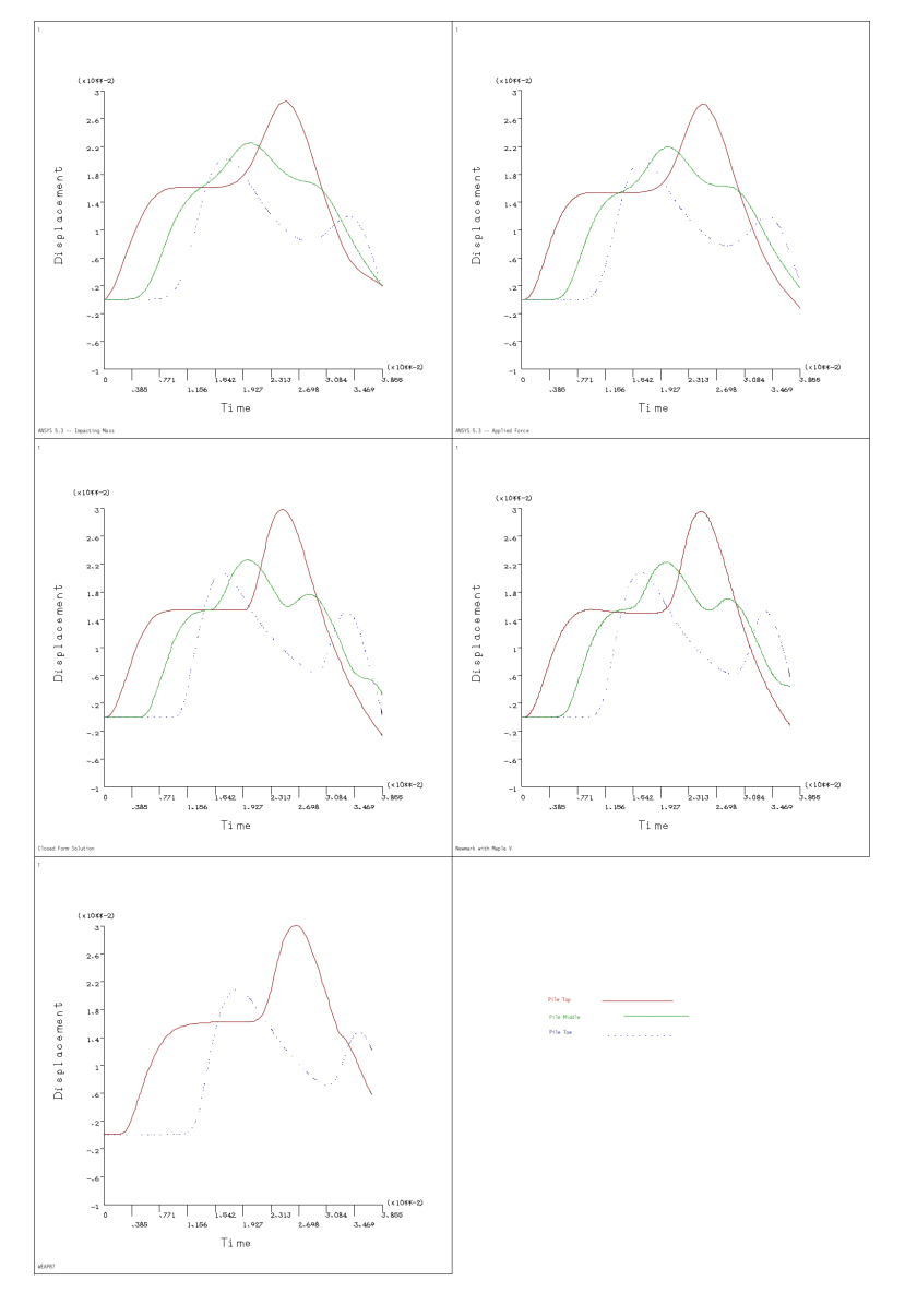
“Locating and quantifying necking in piles through numerical simulation of PIT” cites my paper “Comparison of Numerical Methods to Closed Form Solution for Wave Equation Analysis of Piling”

This recent paper, authored by Tarek Salem, Atef Eraky and Abdallah Almosallamy, was published in Frattura ed Integrità Strutturale. You can obtain the paper here but the gist of it can be found in the preprint, which can be found here.

My original paper was a derivative of my master’s thesis Closed Form Solution of the Wave Equation for Piles. The paper cited can be downloaded here.

The paper states that I used three methods of prediction for wave propagation in piles (WEAP, ANSYS and the closed form solution via MAPLE) to obtain the solution. Although all three of these and more cannot be applied to all solutions, the idea that we can use a variety of software to solve this problem was an important point of the original research, and I hope that this idea will continue to be pursued.

Note on the graphic at the top: it is one of the figures in my original paper, reconstructed in colour from the original CAD drawing. Many of the graphics in my thesis and my paper were done in CAD; we’ve come a long way in computer graphics.

Posted in Geotechnical Engineering

The Physics Of Rocks – Rzhevsky, Novik — Mir Books

In this post, we will see the book The Physics Of Rocks by V. Rzhevsky and G. Novik. About the book This book treats the fundamentals of a new branch of mining sci­ence — rock physics. It defines the subject, the basic trends in rese­arch, and concepts of the physical properties of rock. The mechani­cal, […]

The Physics Of Rocks – Rzhevsky, Novik — Mir Books
Posted in Academic Issues, Geotechnical Engineering

A Quick Preliminary Way to Determine Slope Stability

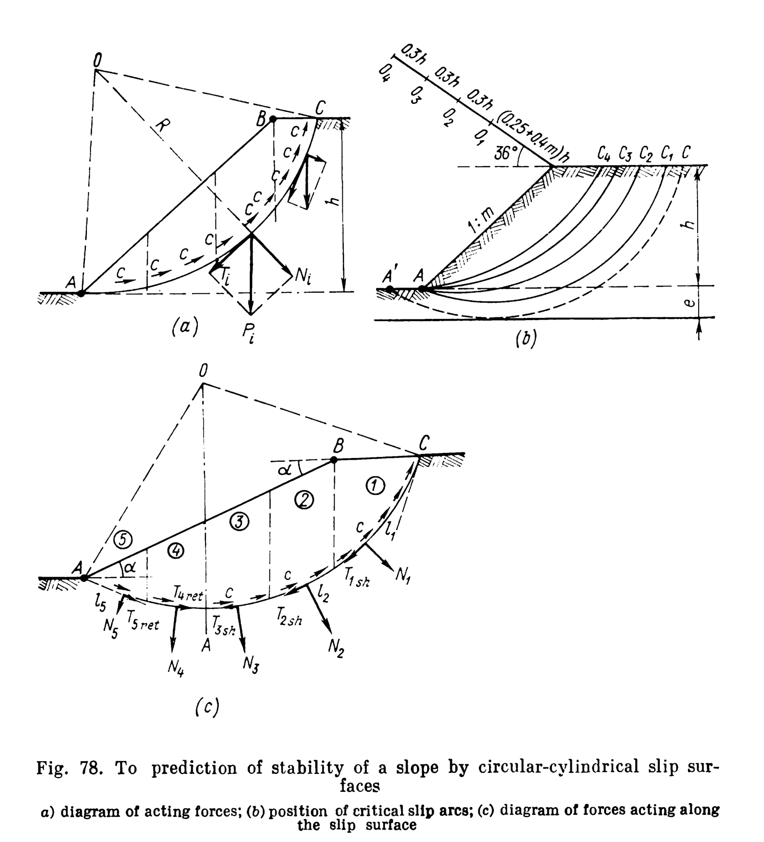
Slope stability for circular failure surfaces is one of those topics where, for a complete solution, solving the problem has involved a computer solution before there were computers. The problem is that it is necessary to a) discretise the problem before solving it, in this case using slices, and b) try a large number of circle centre locations before finding the right one. The problem is illustrated below.

Prediction of slope stability by circular-cylindrical slip surfaces (from Tsytovich (1976))

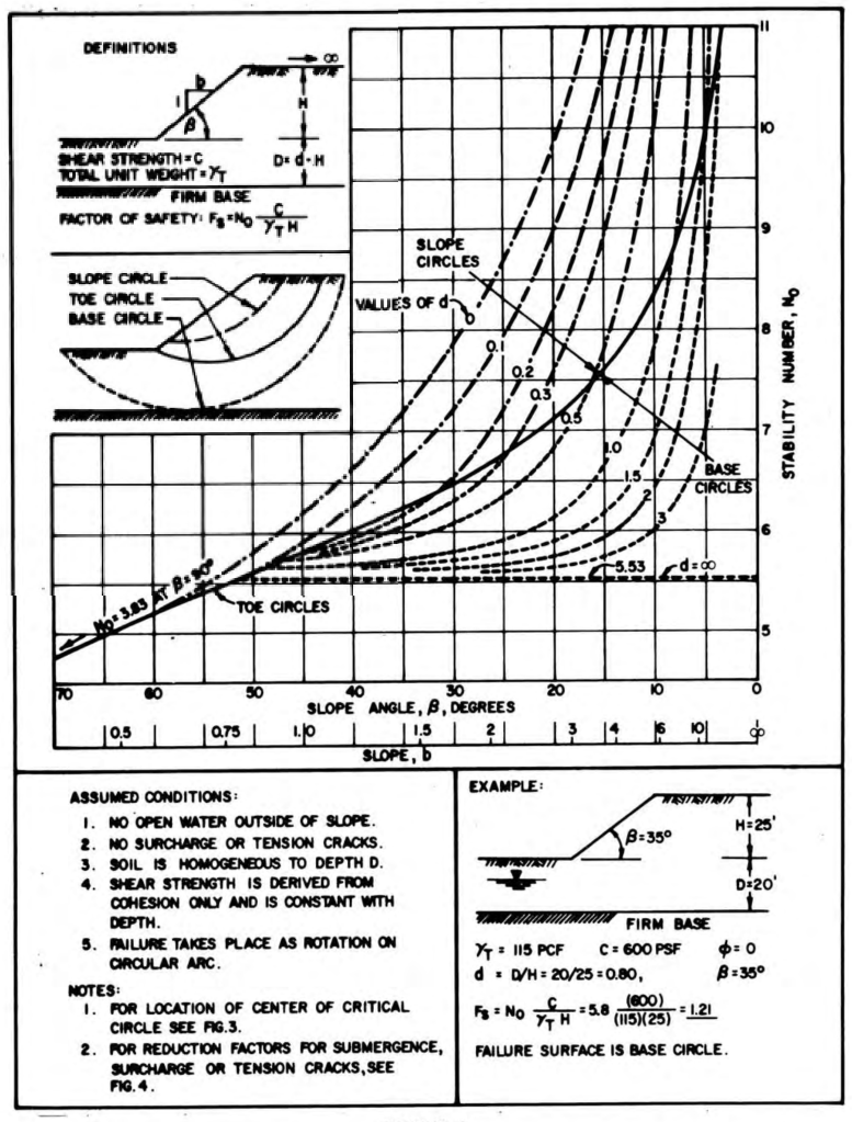
One common method has been to use charts. A commonly used group is the Janbu series of charts, one of which is shown below.

Janbu Chart for cohesive soil (from NAVFAC DM 7.01)

A simpler solution is presented by Tsytovich (1976). The equation proposed there is this:

{\it FS}=\tan(\phi)A+{\frac {cB}{{\it \gamma}\,h}} (1)

where

  • FS = factor of safety
  • \phi = internal frictional angle of the soil
  • c = cohesion of the soil
  • \gamma = unit weight of the soil
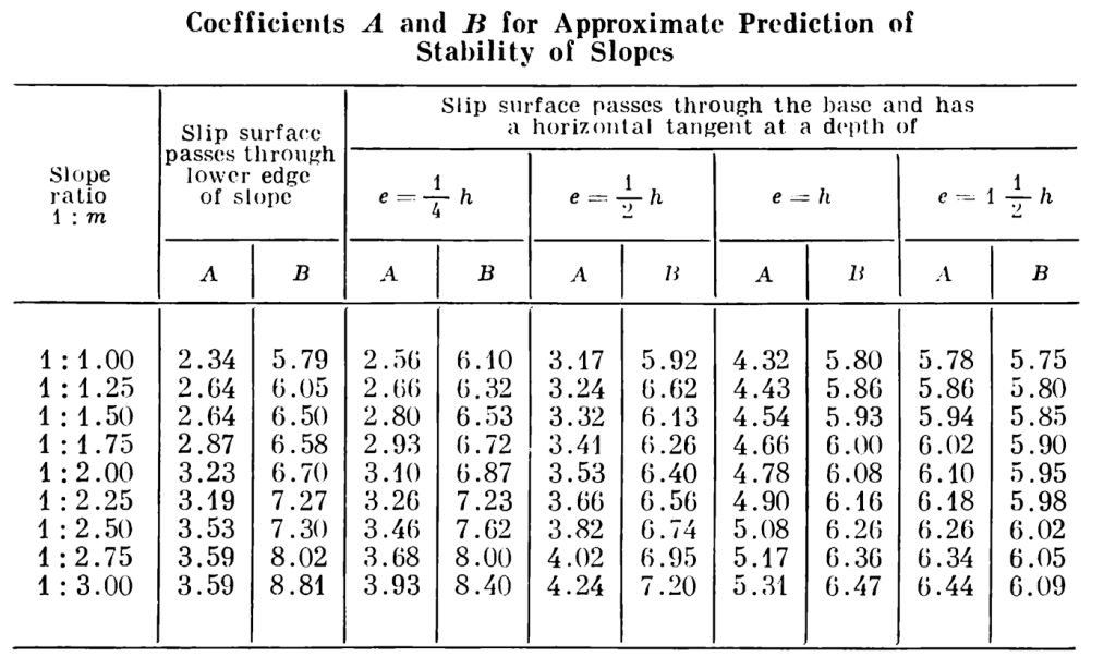
  • A,B = coefficients given below, functions of e and h
  • e = distance from slope toe to hard underground layer (see Figure 78(b))
  • h = height of slope from toe to top (see Figure 78(b))
  • m = second number of slope ratio rise:run (see Figure 78(b))

It is also possible to solve for a maximum height, thus:

h={\frac {cB}{{\it \gamma}\,\left ({\it FS}-\tan(\phi)A\right )}} (2)

Coefficients of A and B for Approximate Prediction of Stability of Slopes (from Tsytovich (1976))

As an example, consider a slope with an angle of 35 degrees and a height of 20′. The soil has an internal friction angle of 15 degrees, a cohesion of 600 psf and a unit weight of 120 pcf. Estimate the factor of safety against slope failure using the method described. For this slope e = 0, so assume the slip surface passes through the lower edge (toe) of the slope.

The slope ratio 1:m is the reciprocal of the tangent of the slope given. Taking the tangent and inverting it gives a slope ratio of 1:1.43. It can be seen by inspection that A = 2.64 and through interpolation B = 6.38. Direct substitution yields a factor of safety of 2.3.

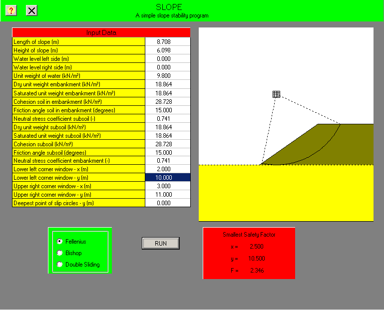
As a comparison we use the Slope program from our Soil Mechanics Course, the results are shown below using Fellenius’ Method.

The factor of safety is very close. If we used Bishop’s Method in the program, we could expect the factor of safety to increase. One thing absent from this problem is the presence of water, which always complicates slope stability analysis.

If we consider the example problem from the Janbu chart above, Equation (1) reduces to the equation for FS on the chart provided that B = N_o . Doing the linear interpolation yields B = 6.05 , which is higher than the N_o = 5.8 on the chart, or FS = 1.26 .

Obviously the method is not suitable for final design but it is interesting for producing preliminary results for a problem which has traditionally been computationally difficult.

Posted in Academic Issues, Geotechnical Engineering

Foundation Design and Analysis: Shallow Foundations, Bearing Capacity

Other resources:

Note: this is an update from an earlier lecture, which actually combines two lectures as well. Some new equipment was used; however, the “live screen” method didn’t quite work out, which meant that I ended up putting the slides in the video during video editing. Since I point to the slides from time to time, this may end up with some awkward moments. I apologise for any inconvenience.