
Our last cases to consider are the cases of uniaxial loading. Although these cases may seem trivial, they are important. As it was with the two-dimensional cases of plane stress and plane strain, there are two variations of the uniaxial loading to consider: uniaxial stress and uniaxial strain.
Uniaxial Stress
We start by considering the constitutive equation of the three-dimensional case, which is
![\left[\begin{array}{cccccc} {\frac{\left(1-\nu\right)\lambda}{\nu}} & \lambda & \lambda & 0 & 0 & 0\\ \noalign{\medskip}\lambda & {\frac{\left(1-\nu\right)\lambda}{\nu}} & \lambda & 0 & 0 & 0\\ \noalign{\medskip}\lambda & \lambda & {\frac{\left(1-\nu\right)\lambda}{\nu}} & 0 & 0 & 0\\ \noalign{\medskip}0 & 0 & 0 & G & 0 & 0\\ \noalign{\medskip}0 & 0 & 0 & 0 & G & 0\\ \noalign{\medskip}0 & 0 & 0 & 0 & 0 & G \end{array}\right]\left[\begin{array}{c} \epsilon_{{x}}\\ \noalign{\medskip}\epsilon_{{y}}\\ \noalign{\medskip}\epsilon_{{z}}\\ \noalign{\medskip}\gamma{}_{{\it xy}}\\ \noalign{\medskip}{\it \gamma}_{{\it yz}}\\ \noalign{\medskip}{\it \gamma}_{{\it zx}} \end{array}\right]=\left[\begin{array}{c} \sigma_{{x}}\\ \noalign{\medskip}\sigma_{{y}}\\ \noalign{\medskip}\sigma_{{z}}\\ \noalign{\medskip}\tau_{{\it xy}}\\ \noalign{\medskip}\tau_{{\it yz}}\\ \noalign{\medskip}\tau_{{\it zx}} \end{array}\right]](https://s0.wp.com/latex.php?latex=%5Cleft%5B%5Cbegin%7Barray%7D%7Bcccccc%7D+%7B%5Cfrac%7B%5Cleft%281-%5Cnu%5Cright%29%5Clambda%7D%7B%5Cnu%7D%7D+%26+%5Clambda+%26+%5Clambda+%26+0+%26+0+%26+0%5C%5C+%5Cnoalign%7B%5Cmedskip%7D%5Clambda+%26+%7B%5Cfrac%7B%5Cleft%281-%5Cnu%5Cright%29%5Clambda%7D%7B%5Cnu%7D%7D+%26+%5Clambda+%26+0+%26+0+%26+0%5C%5C+%5Cnoalign%7B%5Cmedskip%7D%5Clambda+%26+%5Clambda+%26+%7B%5Cfrac%7B%5Cleft%281-%5Cnu%5Cright%29%5Clambda%7D%7B%5Cnu%7D%7D+%26+0+%26+0+%26+0%5C%5C+%5Cnoalign%7B%5Cmedskip%7D0+%26+0+%26+0+%26+G+%26+0+%26+0%5C%5C+%5Cnoalign%7B%5Cmedskip%7D0+%26+0+%26+0+%26+0+%26+G+%26+0%5C%5C+%5Cnoalign%7B%5Cmedskip%7D0+%26+0+%26+0+%26+0+%26+0+%26+G+%5Cend%7Barray%7D%5Cright%5D%5Cleft%5B%5Cbegin%7Barray%7D%7Bc%7D+%5Cepsilon_%7B%7Bx%7D%7D%5C%5C+%5Cnoalign%7B%5Cmedskip%7D%5Cepsilon_%7B%7By%7D%7D%5C%5C+%5Cnoalign%7B%5Cmedskip%7D%5Cepsilon_%7B%7Bz%7D%7D%5C%5C+%5Cnoalign%7B%5Cmedskip%7D%5Cgamma%7B%7D_%7B%7B%5Cit+xy%7D%7D%5C%5C+%5Cnoalign%7B%5Cmedskip%7D%7B%5Cit+%5Cgamma%7D_%7B%7B%5Cit+yz%7D%7D%5C%5C+%5Cnoalign%7B%5Cmedskip%7D%7B%5Cit+%5Cgamma%7D_%7B%7B%5Cit+zx%7D%7D+%5Cend%7Barray%7D%5Cright%5D%3D%5Cleft%5B%5Cbegin%7Barray%7D%7Bc%7D+%5Csigma_%7B%7Bx%7D%7D%5C%5C+%5Cnoalign%7B%5Cmedskip%7D%5Csigma_%7B%7By%7D%7D%5C%5C+%5Cnoalign%7B%5Cmedskip%7D%5Csigma_%7B%7Bz%7D%7D%5C%5C+%5Cnoalign%7B%5Cmedskip%7D%5Ctau_%7B%7B%5Cit+xy%7D%7D%5C%5C+%5Cnoalign%7B%5Cmedskip%7D%5Ctau_%7B%7B%5Cit+yz%7D%7D%5C%5C+%5Cnoalign%7B%5Cmedskip%7D%5Ctau_%7B%7B%5Cit+zx%7D%7D+%5Cend%7Barray%7D%5Cright%5D+&bg=ffffff&fg=777777&s=0&c=20201002)
For uniaxial stress, the following parameters are zero:


As a result, stress and strain vectors are
![\epsilon=\left[\begin{array}{c} \epsilon_{{x}}\\ \noalign{\medskip}\epsilon_{{y}}\\ \noalign{\medskip}\epsilon_{{z}}\\ \noalign{\medskip}0\\ \noalign{\medskip}0\\ \noalign{\medskip}0 \end{array}\right]](https://s0.wp.com/latex.php?latex=%5Cepsilon%3D%5Cleft%5B%5Cbegin%7Barray%7D%7Bc%7D+%5Cepsilon_%7B%7Bx%7D%7D%5C%5C+%5Cnoalign%7B%5Cmedskip%7D%5Cepsilon_%7B%7By%7D%7D%5C%5C+%5Cnoalign%7B%5Cmedskip%7D%5Cepsilon_%7B%7Bz%7D%7D%5C%5C+%5Cnoalign%7B%5Cmedskip%7D0%5C%5C+%5Cnoalign%7B%5Cmedskip%7D0%5C%5C+%5Cnoalign%7B%5Cmedskip%7D0+%5Cend%7Barray%7D%5Cright%5D+&bg=ffffff&fg=777777&s=0&c=20201002)
![\sigma=\left[\begin{array}{c} \sigma_{{x}}\\ \noalign{\medskip}0\\ \noalign{\medskip}0\\ \noalign{\medskip}0\\ \noalign{\medskip}0\\ \noalign{\medskip}0 \end{array}\right]](https://s0.wp.com/latex.php?latex=%5Csigma%3D%5Cleft%5B%5Cbegin%7Barray%7D%7Bc%7D+%5Csigma_%7B%7Bx%7D%7D%5C%5C+%5Cnoalign%7B%5Cmedskip%7D0%5C%5C+%5Cnoalign%7B%5Cmedskip%7D0%5C%5C+%5Cnoalign%7B%5Cmedskip%7D0%5C%5C+%5Cnoalign%7B%5Cmedskip%7D0%5C%5C+%5Cnoalign%7B%5Cmedskip%7D0+%5Cend%7Barray%7D%5Cright%5D+&bg=ffffff&fg=777777&s=0&c=20201002)
It’s worth noting that we’ve zeroed out the shear stresses and strains. That’s because, with a uniaxial loading, the x, y and z stresses and strains are guaranteed to be principal stresses and strains, and thus the shear stresses are zero. We will see that the shear stresses and strains will return with axis rotation.
In any case, doing the usual multiplications and inverse multiplications, we have the following:
![\epsilon=\left[\begin{array}{c} \epsilon_{{x}}\\ \noalign{\medskip}\epsilon_{{y}}\\ \noalign{\medskip}\epsilon_{{z}}\\ \noalign{\medskip}0\\ \noalign{\medskip}0\\ \noalign{\medskip}0 \end{array}\right]=\left[\begin{array}{c} -{\frac{\nu\,\sigma_{{x}}}{\lambda\,\left(-1+\nu+2\,{\nu}^{2}\right)}}\\ \noalign{\medskip}{\frac{{\nu}^{2}\sigma_{{x}}}{\lambda\,\left(-1+\nu+2\,{\nu}^{2}\right)}}\\ \noalign{\medskip}{\frac{{\nu}^{2}\sigma_{{x}}}{\lambda\,\left(-1+\nu+2\,{\nu}^{2}\right)}}\\ \noalign{\medskip}0\\ \noalign{\medskip}0\\ \noalign{\medskip}0 \end{array}\right]](https://s0.wp.com/latex.php?latex=%5Cepsilon%3D%5Cleft%5B%5Cbegin%7Barray%7D%7Bc%7D+%5Cepsilon_%7B%7Bx%7D%7D%5C%5C+%5Cnoalign%7B%5Cmedskip%7D%5Cepsilon_%7B%7By%7D%7D%5C%5C+%5Cnoalign%7B%5Cmedskip%7D%5Cepsilon_%7B%7Bz%7D%7D%5C%5C+%5Cnoalign%7B%5Cmedskip%7D0%5C%5C+%5Cnoalign%7B%5Cmedskip%7D0%5C%5C+%5Cnoalign%7B%5Cmedskip%7D0+%5Cend%7Barray%7D%5Cright%5D%3D%5Cleft%5B%5Cbegin%7Barray%7D%7Bc%7D+-%7B%5Cfrac%7B%5Cnu%5C%2C%5Csigma_%7B%7Bx%7D%7D%7D%7B%5Clambda%5C%2C%5Cleft%28-1%2B%5Cnu%2B2%5C%2C%7B%5Cnu%7D%5E%7B2%7D%5Cright%29%7D%7D%5C%5C+%5Cnoalign%7B%5Cmedskip%7D%7B%5Cfrac%7B%7B%5Cnu%7D%5E%7B2%7D%5Csigma_%7B%7Bx%7D%7D%7D%7B%5Clambda%5C%2C%5Cleft%28-1%2B%5Cnu%2B2%5C%2C%7B%5Cnu%7D%5E%7B2%7D%5Cright%29%7D%7D%5C%5C+%5Cnoalign%7B%5Cmedskip%7D%7B%5Cfrac%7B%7B%5Cnu%7D%5E%7B2%7D%5Csigma_%7B%7Bx%7D%7D%7D%7B%5Clambda%5C%2C%5Cleft%28-1%2B%5Cnu%2B2%5C%2C%7B%5Cnu%7D%5E%7B2%7D%5Cright%29%7D%7D%5C%5C+%5Cnoalign%7B%5Cmedskip%7D0%5C%5C+%5Cnoalign%7B%5Cmedskip%7D0%5C%5C+%5Cnoalign%7B%5Cmedskip%7D0+%5Cend%7Barray%7D%5Cright%5D+&bg=ffffff&fg=777777&s=0&c=20201002)
![\sigma=\left[\begin{array}{c} \sigma_{{x}}\\ \noalign{\medskip}0\\ \noalign{\medskip}0\\ \noalign{\medskip}0\\ \noalign{\medskip}0\\ \noalign{\medskip}0 \end{array}\right]=\left[\begin{array}{c} {\frac{\left(1-\nu\right)\lambda\,\epsilon_{{x}}}{\nu}}+\lambda\,\epsilon_{{y}}+\lambda\,\epsilon_{{z}}\\ \noalign{\medskip}\lambda\,\epsilon_{{x}}+{\frac{\left(1-\nu\right)\lambda\,\epsilon_{{y}}}{\nu}}+\lambda\,\epsilon_{{z}}\\ \noalign{\medskip}\lambda\,\epsilon_{{x}}+\lambda\,\epsilon_{{y}}+{\frac{\left(1-\nu\right)\lambda\,\epsilon_{{z}}}{\nu}}\\ \noalign{\medskip}0\\ \noalign{\medskip}0\\ \noalign{\medskip}0 \end{array}\right]](https://s0.wp.com/latex.php?latex=%5Csigma%3D%5Cleft%5B%5Cbegin%7Barray%7D%7Bc%7D+%5Csigma_%7B%7Bx%7D%7D%5C%5C+%5Cnoalign%7B%5Cmedskip%7D0%5C%5C+%5Cnoalign%7B%5Cmedskip%7D0%5C%5C+%5Cnoalign%7B%5Cmedskip%7D0%5C%5C+%5Cnoalign%7B%5Cmedskip%7D0%5C%5C+%5Cnoalign%7B%5Cmedskip%7D0+%5Cend%7Barray%7D%5Cright%5D%3D%5Cleft%5B%5Cbegin%7Barray%7D%7Bc%7D+%7B%5Cfrac%7B%5Cleft%281-%5Cnu%5Cright%29%5Clambda%5C%2C%5Cepsilon_%7B%7Bx%7D%7D%7D%7B%5Cnu%7D%7D%2B%5Clambda%5C%2C%5Cepsilon_%7B%7By%7D%7D%2B%5Clambda%5C%2C%5Cepsilon_%7B%7Bz%7D%7D%5C%5C+%5Cnoalign%7B%5Cmedskip%7D%5Clambda%5C%2C%5Cepsilon_%7B%7Bx%7D%7D%2B%7B%5Cfrac%7B%5Cleft%281-%5Cnu%5Cright%29%5Clambda%5C%2C%5Cepsilon_%7B%7By%7D%7D%7D%7B%5Cnu%7D%7D%2B%5Clambda%5C%2C%5Cepsilon_%7B%7Bz%7D%7D%5C%5C+%5Cnoalign%7B%5Cmedskip%7D%5Clambda%5C%2C%5Cepsilon_%7B%7Bx%7D%7D%2B%5Clambda%5C%2C%5Cepsilon_%7B%7By%7D%7D%2B%7B%5Cfrac%7B%5Cleft%281-%5Cnu%5Cright%29%5Clambda%5C%2C%5Cepsilon_%7B%7Bz%7D%7D%7D%7B%5Cnu%7D%7D%5C%5C+%5Cnoalign%7B%5Cmedskip%7D0%5C%5C+%5Cnoalign%7B%5Cmedskip%7D0%5C%5C+%5Cnoalign%7B%5Cmedskip%7D0+%5Cend%7Barray%7D%5Cright%5D+&bg=ffffff&fg=777777&s=0&c=20201002)
Considering the first rows of Equation (5) gives us

and from the next two rows

It’s possible to formulate the computation of the stresses based on the strains, but in uniaxial loading it is usually easier to know the stresses first.
Although uniaxial loading is common in tensile and compressive stresses of materials such as metals and plastics, in geotechnical engineering it is mainly concentrated in two types of tests: Triaxial tests and Unconfined Compression (UC) tests. Since in Mohr-Coulomb theory we use a maximum shear stress to determine the point of failure, and the shear stresses and strains don’t appear in the above equations, an explanation as to how shear stresses and strains apply is reasonable.
Rather than go into a math-intensive derivation of the problem, recourse to Mohr’s Circle is more instructive.
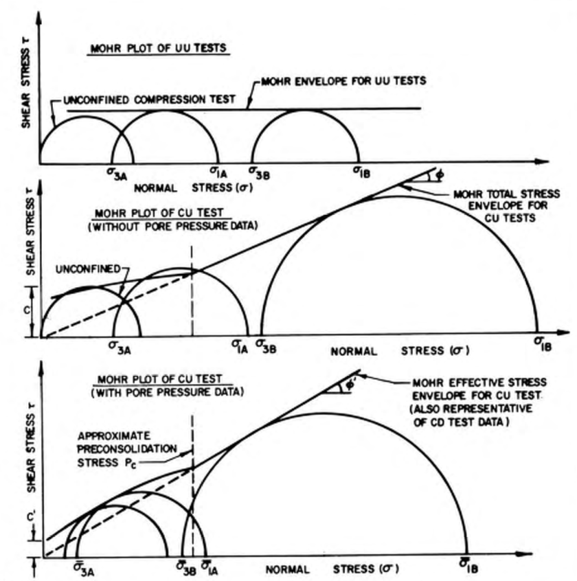
Let’s look at the top diagram from a UC test. The main uniaxial stress 

In the case of materials with internal friction, things are a little more complicated, because the angle from the principal stress to the point where Mohr’s Circle meets the failure envelope is greater than 90 degrees, thus the angle between the centre axis and the failure plane is greater than 45 degrees, and depends upon the interaction of the cohesion and the internal friction angle.
Of course people who actually run these tests will tell you that these specimens don’t always fail along these planes, or simply bulge at failure. That’s because soils don’t always obey Mohr-Coulomb elastic-perfectly plastic failure theory, which is one of those things that makes geotechnical engineering challenging.
Uniaxial Strain
Although this case doesn’t seem at first glance to be very useful, it’s really an important one for geotechnical engineers. We’ll start again with Equation (1) and zero out the following parameters:

Of course Equation (2b) applies as well. Doing this results in the following vectors, and I’ll go ahead and multiply and inversely multiply through as before:
![\epsilon=\left[\begin{array}{c} \epsilon_{{x}}\\ \noalign{\medskip}0\\ \noalign{\medskip}0\\ \noalign{\medskip}0\\ \noalign{\medskip}0\\ \noalign{\medskip}0 \end{array}\right]=\left[\begin{array}{c} -{\frac{\nu\,\sigma_{{x}}}{\lambda\,\left(-1+\nu+2\,{\nu}^{2}\right)}}+{\frac{{\nu}^{2}\sigma_{{y}}}{\lambda\,\left(-1+\nu+2\,{\nu}^{2}\right)}}+{\frac{{\nu}^{2}\sigma_{{z}}}{\lambda\,\left(-1+\nu+2\,{\nu}^{2}\right)}}\\ \noalign{\medskip}{\frac{{\nu}^{2}\sigma_{{x}}}{\lambda\,\left(-1+\nu+2\,{\nu}^{2}\right)}}-{\frac{\nu\,\sigma_{{y}}}{\lambda\,\left(-1+\nu+2\,{\nu}^{2}\right)}}+{\frac{{\nu}^{2}\sigma_{{z}}}{\lambda\,\left(-1+\nu+2\,{\nu}^{2}\right)}}\\ \noalign{\medskip}{\frac{{\nu}^{2}\sigma_{{x}}}{\lambda\,\left(-1+\nu+2\,{\nu}^{2}\right)}}+{\frac{{\nu}^{2}\sigma_{{y}}}{\lambda\,\left(-1+\nu+2\,{\nu}^{2}\right)}}-{\frac{\nu\,\sigma_{{z}}}{\lambda\,\left(-1+\nu+2\,{\nu}^{2}\right)}}\\ \noalign{\medskip}0\\ \noalign{\medskip}0\\ \noalign{\medskip}0 \end{array}\right]](https://s0.wp.com/latex.php?latex=%5Cepsilon%3D%5Cleft%5B%5Cbegin%7Barray%7D%7Bc%7D+%5Cepsilon_%7B%7Bx%7D%7D%5C%5C+%5Cnoalign%7B%5Cmedskip%7D0%5C%5C+%5Cnoalign%7B%5Cmedskip%7D0%5C%5C+%5Cnoalign%7B%5Cmedskip%7D0%5C%5C+%5Cnoalign%7B%5Cmedskip%7D0%5C%5C+%5Cnoalign%7B%5Cmedskip%7D0+%5Cend%7Barray%7D%5Cright%5D%3D%5Cleft%5B%5Cbegin%7Barray%7D%7Bc%7D+-%7B%5Cfrac%7B%5Cnu%5C%2C%5Csigma_%7B%7Bx%7D%7D%7D%7B%5Clambda%5C%2C%5Cleft%28-1%2B%5Cnu%2B2%5C%2C%7B%5Cnu%7D%5E%7B2%7D%5Cright%29%7D%7D%2B%7B%5Cfrac%7B%7B%5Cnu%7D%5E%7B2%7D%5Csigma_%7B%7By%7D%7D%7D%7B%5Clambda%5C%2C%5Cleft%28-1%2B%5Cnu%2B2%5C%2C%7B%5Cnu%7D%5E%7B2%7D%5Cright%29%7D%7D%2B%7B%5Cfrac%7B%7B%5Cnu%7D%5E%7B2%7D%5Csigma_%7B%7Bz%7D%7D%7D%7B%5Clambda%5C%2C%5Cleft%28-1%2B%5Cnu%2B2%5C%2C%7B%5Cnu%7D%5E%7B2%7D%5Cright%29%7D%7D%5C%5C+%5Cnoalign%7B%5Cmedskip%7D%7B%5Cfrac%7B%7B%5Cnu%7D%5E%7B2%7D%5Csigma_%7B%7Bx%7D%7D%7D%7B%5Clambda%5C%2C%5Cleft%28-1%2B%5Cnu%2B2%5C%2C%7B%5Cnu%7D%5E%7B2%7D%5Cright%29%7D%7D-%7B%5Cfrac%7B%5Cnu%5C%2C%5Csigma_%7B%7By%7D%7D%7D%7B%5Clambda%5C%2C%5Cleft%28-1%2B%5Cnu%2B2%5C%2C%7B%5Cnu%7D%5E%7B2%7D%5Cright%29%7D%7D%2B%7B%5Cfrac%7B%7B%5Cnu%7D%5E%7B2%7D%5Csigma_%7B%7Bz%7D%7D%7D%7B%5Clambda%5C%2C%5Cleft%28-1%2B%5Cnu%2B2%5C%2C%7B%5Cnu%7D%5E%7B2%7D%5Cright%29%7D%7D%5C%5C+%5Cnoalign%7B%5Cmedskip%7D%7B%5Cfrac%7B%7B%5Cnu%7D%5E%7B2%7D%5Csigma_%7B%7Bx%7D%7D%7D%7B%5Clambda%5C%2C%5Cleft%28-1%2B%5Cnu%2B2%5C%2C%7B%5Cnu%7D%5E%7B2%7D%5Cright%29%7D%7D%2B%7B%5Cfrac%7B%7B%5Cnu%7D%5E%7B2%7D%5Csigma_%7B%7By%7D%7D%7D%7B%5Clambda%5C%2C%5Cleft%28-1%2B%5Cnu%2B2%5C%2C%7B%5Cnu%7D%5E%7B2%7D%5Cright%29%7D%7D-%7B%5Cfrac%7B%5Cnu%5C%2C%5Csigma_%7B%7Bz%7D%7D%7D%7B%5Clambda%5C%2C%5Cleft%28-1%2B%5Cnu%2B2%5C%2C%7B%5Cnu%7D%5E%7B2%7D%5Cright%29%7D%7D%5C%5C+%5Cnoalign%7B%5Cmedskip%7D0%5C%5C+%5Cnoalign%7B%5Cmedskip%7D0%5C%5C+%5Cnoalign%7B%5Cmedskip%7D0+%5Cend%7Barray%7D%5Cright%5D+&bg=ffffff&fg=777777&s=0&c=20201002)
![\sigma=\left[\begin{array}{c} \sigma_{{x}}\\ \noalign{\medskip}\sigma_{y}\\ \noalign{\medskip}\sigma_{z}\\ \noalign{\medskip}0\\ \noalign{\medskip}0\\ \noalign{\medskip}0 \end{array}\right]=\left[\begin{array}{c} {\frac{\left(1-\nu\right)\lambda\,\epsilon_{{x}}}{\nu}}\\ \noalign{\medskip}\lambda\,\epsilon_{{x}}\\ \noalign{\medskip}\lambda\,\epsilon_{{x}}\\ \noalign{\medskip}0\\ \noalign{\medskip}0\\ \noalign{\medskip}0 \end{array}\right]](https://s0.wp.com/latex.php?latex=%5Csigma%3D%5Cleft%5B%5Cbegin%7Barray%7D%7Bc%7D+%5Csigma_%7B%7Bx%7D%7D%5C%5C+%5Cnoalign%7B%5Cmedskip%7D%5Csigma_%7By%7D%5C%5C+%5Cnoalign%7B%5Cmedskip%7D%5Csigma_%7Bz%7D%5C%5C+%5Cnoalign%7B%5Cmedskip%7D0%5C%5C+%5Cnoalign%7B%5Cmedskip%7D0%5C%5C+%5Cnoalign%7B%5Cmedskip%7D0+%5Cend%7Barray%7D%5Cright%5D%3D%5Cleft%5B%5Cbegin%7Barray%7D%7Bc%7D+%7B%5Cfrac%7B%5Cleft%281-%5Cnu%5Cright%29%5Clambda%5C%2C%5Cepsilon_%7B%7Bx%7D%7D%7D%7B%5Cnu%7D%7D%5C%5C+%5Cnoalign%7B%5Cmedskip%7D%5Clambda%5C%2C%5Cepsilon_%7B%7Bx%7D%7D%5C%5C+%5Cnoalign%7B%5Cmedskip%7D%5Clambda%5C%2C%5Cepsilon_%7B%7Bx%7D%7D%5C%5C+%5Cnoalign%7B%5Cmedskip%7D0%5C%5C+%5Cnoalign%7B%5Cmedskip%7D0%5C%5C+%5Cnoalign%7B%5Cmedskip%7D0+%5Cend%7Barray%7D%5Cright%5D+&bg=ffffff&fg=777777&s=0&c=20201002)
Extracting the important results,


Although it may seem esoteric, this condition is actually important because it simulates confined specimens under uniaxial load. The best known of these, of course, is consolidation testing and all of the variations of that which are employed. It may seem strange to employ elastic theory in this situation, but that speaks to Jean-Louis Briaud’s pet peeve regarding consolidation testing and the partial solution to the problem he poses. Some discussion of this relationship can also be found in Verruijt.
The whole concept of confined specimens is based on the fact that the entire ground upon which we build is a confined specimen, confined by the semi-infinite soil surrounding the loaded portion. Thus this unlikely looking case is very relevant for real geotechnical engineering.

2 thoughts on “Constitutive Elasticity Equations: Uniaxial Cases”