A couple of years ago our bookstore was reorganised to put our offerings in wider distribution. Some of the discontinued titles are being put back into print, directly from the printer. Click on the title or image to to order.
Bearing Capacity and Settlement
This is actually two books in one. We also offer for download two software packages described in the book:
- Program VDISPL, Vertical Displacements of Shallow Foundations
- Program AXILTR (Bearing Capacity Analysis) Available
Bearing Capacity of Soils

This manual presents guidelines for calculation of the bearing capacity of soil under shallow and deep foundations supporting various types of structures and embankments. Principles for evaluating bearing capacity presented in this manual are applicable to numerous types of structures such as buildings and houses, towers and storage tanks, fills, embankments and dams. These guidelines may be helpful in determining soils that will lead to bearing capacity failure or excessive settlements for given foundations and loads. Consideration should be given to obtaining the services and advice of specialists and consultants in foundation design where foundation conditions are unusual or critical or structures are economically significant.
Settlement Analysis
This manual presents guidelines for calculation of vertical displacements and settlement of soil under shallow foundations (mats and footings) supporting various types of structures and under embankments. Vertical displacements and settlement caused by change in stress and water content are described in this manual. Limitations of these movements required for different structures are also described. Various types of settlement are discussed in detail, including settlement due to elastic deformation, consolidation, secondary compression and creep, settlement due to dynamic loads, and expansive and collapsible soils. Solutions to soil movement problems are discussed and detailed. Deep foundations and landfills are also discussed.
Retaining and Flood Walls

This book presents information on the design of retaining walls and inland and coastal flood walls. Retaining walls are defined as any wall that restrains material to maintain a difference in elevation.
A floodwall is defined as any wall having as its principal function the prevention of loading of adjacent land. Not specifically covered in this book are seawalls which are defined as structures separating land and water areas, primarily designed to prevent erosion and other damage due to wave action. They are frequently built at the edge of the water, but can be built inland to withstand periods of high water.
Seawalls are generally characterized by a massive cross section and a seaward face shaped to dissipate wave energy. Coastal flood walls, however, are generally located landward of the normal high water line so that they are inundated only by hurricane or other surge tide and have the smooth-faced cantilever stems shown in this book. This book also describes procedures for the design of retaining and flood walls on shallow foundations, i.e., those bearing directly on rock or soil.
Seismic Design of Waterfront Retaining Structures
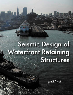
This book deals with the soil mechanics aspects of the design of waterfront retaining structures built to withstand the effects of earthquake loadings. It addresses the stability and movement of gravity retaining walls and anchored sheet pile walls, and the dynamic forces against the walls of drydocks and U-frame locks. It also contains one of the most complete descriptions of lateral earth pressure theory available anywhere.
The effects of wall displacements, submergence, liquefaction potential, and excess pore water pressures, as well as inertial and hydrodynamic forces, are incorporated in the design procedures. Several new computational procedures are described in this report.
The procedures used to calculate the dynamic earth pressures acting on retaining structures consider the magnitude of wall displacements. For example, dynamic active earth pressures are computed for walls that retain yielding backfills, i.e., backfills that undergo sufficient displacements during seismic events to mobilize fully the shear resistance of the soil. For smaller wall movements, the shear resistance of the soil is not fully mobilized and the dynamic earth pressures acting on those walls are greater because the soil comprising the backfill does not yield, i.e., a nonyielding backfill. Procedures for incorporating the effects of submergence within the earth pressure computations, including consideration of excess pore water pressures, are described.
Military Soils Engineering

Originally written to supply engineer officers and noncommissioned officers with doctrinal tenets and technical facts concerning the use and management of soils during military construction, Military Soils Engineering is one of the most practical guides to basic engineering geology and soil mechanics available. It provides guidance in evaluating soil conditions, predicting soil behavior under varying conditions, and solving soil problems principally related to military operations but applicable to the construction of a wide variety of foundations and earth structures.
Construction in a military theater of operations is normally limited to roads, airfields, and structures. This manual emphasizes the soils engineering aspects of road and airfield construction. The references included in the manual give detailed information on other soils engineering topics that are discussed in general terms.
In addition to this, the manual:
- Provides a discussion of the formation and characteristics of soil and the Unified System of soil classification, used by the United States (US) Army and most geotechnical engineers;
- Gives an overview of classification systems used by AASHTO and the Department of Agriculture;
- Describes the compaction of soils and quality control, settlement and shearing resistance of soils;
- Describes the movement of water through soils, frost action, and the bearing capacity of soils that serve as foundations, slopes, embankments, dikes, dams, and earth-retaining structures; and
- Has a detailed description of the geologic factors that affect the properties and occurrences of natural mineral/soil construction materials used to build a wide variety of structures.
Military Soils Engineering is an indispensable reference for geotechnical engineers, engineering geologists and laboratory and field technicians.
Dam Safety
This is a combination of two authoritative documents on this vital subject.
Federal Guidelines for Dam Safety (FEMA 93): These guidelines apply to management practices for dam safety of all Federal agencies responsible for the planning, design, construction, operation, or regulation of dams. They are not intended as guidelines or standards for the technology of dams. The basic principles of the guidelines apply to all dams. However, reasonable judgments need to be made in their application commensurate with each dam’s size, complexity, and hazard. Federal agencies have a good record and generally sound practices on dam safety. These guidelines are intended to promote management control of dam safety and a common approach to dam safety practices by all the agencies. Although the guidelines are intended for and applicable to all agencies, it is recognized that the methods of the degree of application will vary depending on the agency mission and functions.
Safety of Dams—Policy and Procedures (U.S. Army Corps of Engineers ER 1110-2-1156): This regulation prescribes the guiding principles, policy, organization, responsibilities, and procedures for implementation of risk- informed dam safety program activities and a dam safety portfolio risk management process within the United States Army, Corps of Engineers (USACE). Risk is defined as a measure of the probability and severity of undesirable consequences or outcome. The purpose and intent of this regulation is to ensure that responsible officials at all levels within the Corps of Engineers implement and maintain a strong dam safety program in compliance with “Federal Guidelines for Dam Safety.” The program ensures that all dams and appurtenant structures are designed, constructed, and operated safely and effectively under all conditions, based on the following dam safety and dam safety program purposes, as adopted by the Interagency Committee on Dam Safety (ICODS).