
Part of Soils in Construction‘s presentation of dewatering is this topic. I cover it in my treatment of flow nets in Soil Mechanics: Groundwater and Permeability II; however, Soils in Construction uses a less computationally intensive approach. In this piece I’ll explain that, give some better graphics than the book had available at the time of publication, and compare them with the flow net/FEA results I discussed in my Soil Mechanics course.
Let us consider the problem of a braced cut, which is commonly used for “cut and cover” construction. Such a construction is shown at the right. One of the challenges of temporary works such as this is to insure that a) there is sufficient pumping capacity to keep the “steel trench” dry, and b) the hydraulic gradient of the water coming up into the trench is sufficiently low to avoid soil boiling and bottom heave due to that soil boiling. (Bottom heave can take place due to other factors as well.) An example of that (showing a flow net) is below to the left.
Because the cut is internally braced, it is usually possible to make the sheeting walls simply penetrate to just below the bottom of the trench. However, in order to mitigate the effects of water flowing from around the cut into the bottom, the sheeting can be extended. The idea is that, the longer the extensions, the longer distance the water has to flow, the increased resistance of the soil to flow, and the lower the hydraulic gradients, which both reduce the flow overall and the possibility that the soil at the bottom of the trench will boil, i.e., enter into a quick condition.
Soils in Construction shows two methods of dealing with this problem:
- A “rule of thumb” for sheeting extension; and
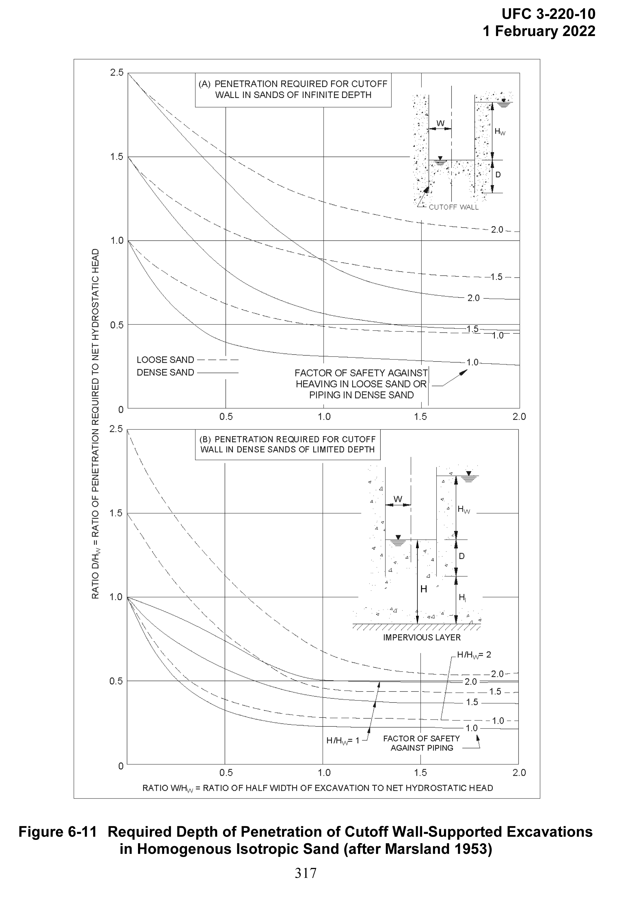
- Charts to determine the minimum extension of the sheeting. These were developed by Marsland (1953). In the book they were taken from NAVFAC DM 7.01, but since the book’s publication NAVFAC DM 7.1 has redone the graphics, and you can see that below (and click on it to download). It is important to note that there is an error in the lower part of this figure; I checked it against Marsland (1953) and have modified it a bit to restore it to Marsland’s original formulation, the following example will show how it is supposed to be used.
Example Problem
I have used this example for many years and feature it in Soil Mechanics: Groundwater and Permeability II. Consider the braced cut shown below.

The parameters for this problem are as follows:
- Braced Sheet Piling Excavation
- Depth of excavation = 38’
- Width of excavation = 32’
- Impervious layer 20’ below the toe of the sheeting
- Length of Sheet Piling = 66’
- Water table at the excavation level on the excavation side
- Water table 6’ below the top of the sheeting on the soil side
- Variables for chart above
- Hw = 38 – 6 = 32′
- D = 66 – 38 = 28′
- Hl = 20′
- H = D + Hl = 28 + 20 = 48′
- W = 16′
- Even though the graphic for the problem doesn’t show it, the problem statement indicates an impervious layer below the excavation; thus, we will use the lower chart for this problem.
- Soil Conditions
- Uniform medium sand, k = 0.0003 ft/sec
- Saturated Unit Weight = 115 pcf
We need to, one way or another, insure that the design does not experience soil boiling.
The “rule of thumb” in Soils in Construction states that “the depth of penetration of the cut-off wall below the bottom of the excavation should be a third of the “length” computed. For this wall, the ratio is 28/66 = 42%, which means the rule of thumb is achieved.
Turning to the chart above, we must compute three quantities:
- The x-axis ratio of half width of excavation to net hydrostatic head, or W/Hw = 16/32 = 0.5;
- the y-axis ratio of penetration required to net hydrostatic head, or D/Hw = 28/32 = 0.875; and
- the ratio of the depth between the bottom of the excavation and the impervious layer to the net hydrostatic head, or H/Hw = 48/32 = 1.5.
In this case we only have two values of H/Hw to work with: 1 and 2. For H/Hw = 1, FS ~ 2.5 (this is a very rough extrapolation.) For H/Hw = 2, FS = 1.75. Since H/Hw = 1.5 is in the middle between the two, the FS = (2.5+1.75)/2 = 2.125.
If we want to check our results by neglecting the impervious layer, we use the upper chart, and assuming the soil is closer to being a loose sand, FS ~ 1.4.
So how does this all compare to a flow net/FEA result? Same is given below.
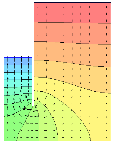
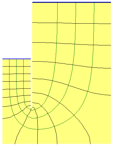
At the right is a flow net generated by the finite element program SEEP-W. At the left is a chart showing the direction of the water flow (arrows) and the hydraulic head (coloured bands.) An in-depth explanation of these can be found at Soil Mechanics: Groundwater and Permeability II. The results are as follows:
- Gradient at bottom of excavation = 0.48
- Factor of safety = 1.77
- Total flow = 1.02 gpm/ft of wall
The critical hydraulic gradient, computed by the methods shown in Computing Pore Water Pressure and Effective Stress in Upward (and Downward) Flow in Soil, is 115/62.4 – 1 = 0.843, which checks with the factor of safety for the actual gradient.
The factor of safety from the chart ignoring the presence of the impervious layer is the closest to the FEA/flow net result. For the chart with the impervious layer, the extrapolation for the lower factor of safety should perhaps be ignored.
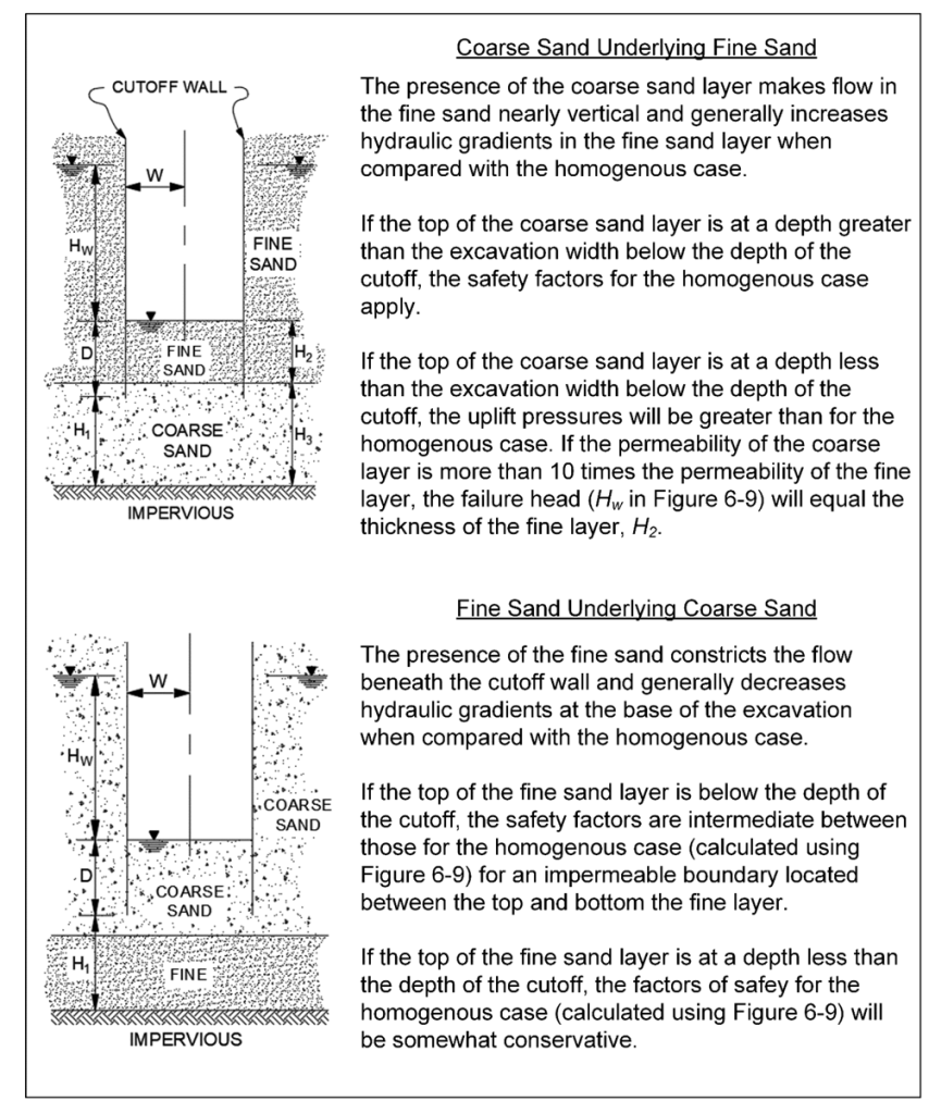
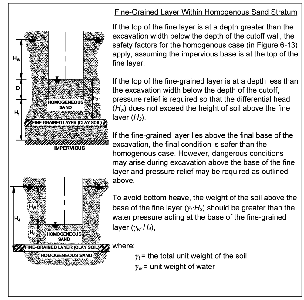
A couple of other charts (based on Marsland (1953)) are shown below.
References
- Marsland, A.R. 1953. “Model Experiments to Study the Influence of Seepage on the Stability of a Sheeted Excavation in Sand.” Geotechnique, 3(6), 223-241.

How do you design sheet pile for marine application such that there will be no collapse if sheet piles are used as cofferdam?
How to design the wales (horizontal supports, its distance between another wales assuming the depth of water is 6 meters?
LikeLike
I deal with both questions in Sheet Pile Design by Pile Buck. With sheet pile cofferdams in water the main lateral load on the sheeting is the hydrostatic force of the surrounding water. The wales can basically be designed as simply supported beams, transferring the loads per unit length of the sheeting to the braces.
LikeLike