
Generally speaking, in Soil Mechanics courses elastic solutions on semi-infinite half spaces are presented to allow the geotechincal engineer to estimate the stresses induced in a soil by a load at the surface. Also presented in Soil Mechanics courses are charts and equations to estimate the lateral pressures on retaining walls induced by vertical loads on the surface behind the retaining walls. How either of these came into being is generally not explained; additionally, the fact that they are related is not explained either. The purpose of this article is to explain that relationship and, in the case of the retaining walls, how the original equations have been modified to suit experimental data. For simplicity’s sake, the discussed will be restricted to line loads.
The Original Equations: Flamant
As pointed out by Verruijt, the original equation for the stresses (vertical, horizontal and shear) were first set forth by Flamant in 1892. The equations are shown below.
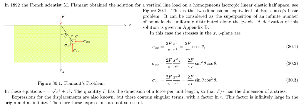
The derivation of this equation can be found here or in Verruijt. Note carefully that the vertical load induces stresses in the horizontal direction (and in shear) as well as the vertical direction.
Verruijt then shows the following:
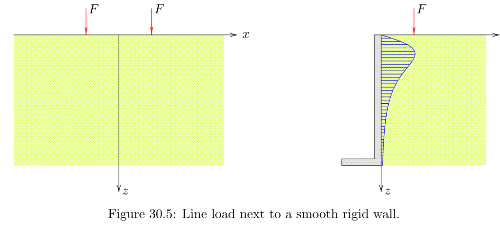
Basically, by static equilibrium, if you replace the left half of the two mirrored loads (on the left) with a rigid wall, the horizontal stresses would be the same on the centre axis/wall as induced by two line loads. The resulting stresses and the resultant for the stress distribution are given below.
The Modified Equations: Terzaghi
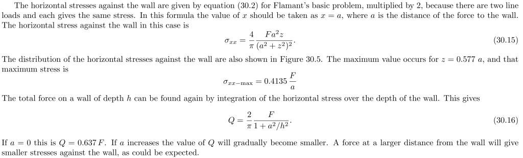
Generally, however, these equations are not presented in books such as DM 7, Sheet Pile Design by Pile Buck or others in this exact form. The following chart (frequently copied) comes from the Soils and Foundations Manual:
The line load is in the upper right hand corner. For values of m (the ratio of the distance from the line load to the wall over the height of the wall) greater than or equal to 0.4, the two results are the same. For those less than that, they are different. (In Verruijt’s notation, m = a/z.) The difference is because most books use the formulation of Terzaghi (1954). He explains the difference as follows:
However, the application of the line load tends to produce a lateral deflection of the vertical section, and the flexural rigidity of the bulkhead interferes with that deflection…However, for values smaller than (m=)0.4, the discrepancy between observed and computed values increases with decreasing values values of m…
From Terzaghi, K. (1954) “Anchored Bulkheads.” Transactions of the American Society of Civil Engineers, Vol. 119, Issue 1.
The whole issue of the flexibility of the retaining wall has been the chief complicating factor in this discussion, going back to Spangler’s tests in the 1930’s.
Comparing the Two Solutions
As an illustration, consider the pressure distribution situation when m=0.3:
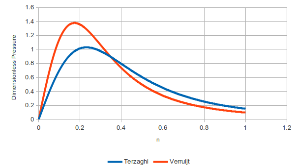
The pressures have been made dimensionless for generalisation. The Flamant solution comes to a higher peak nearer to the surface but falls off more rapidly down the wall. Terzaghi’s solution is more evenly distributed.
Now consider the situation at m=0.5:
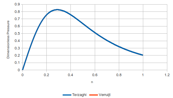
The two are identical in this range.
We can also consider the resultants as well:
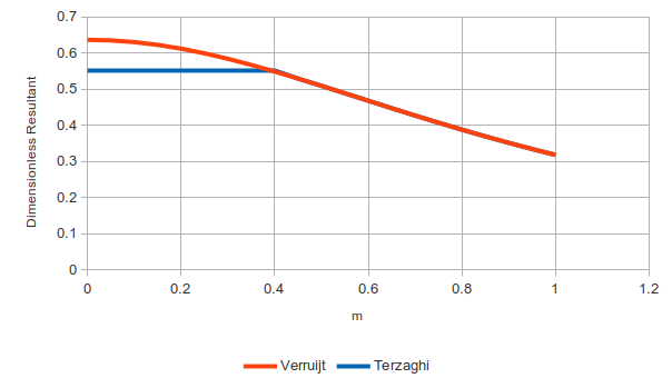
The y-axis is made dimensionless by dividing the resultant by the vertical line load. For values of m less than or equal to 0.4, the results are different; for greater, they are the same.
In general, we can say that Flamant’s original formulation is more conservative. In the event that a deeper understanding of the interaction of surface loads with a retaining wall is desired, a finite element analysis needs to be done.

2 thoughts on “The Difference Between Flamant’s and Terzaghi’s Solution for Line Loads Behind Retaining Walls”